Table of Contents
Advertisement
Advertisement
Table of Contents

Related Manuals for TR-Electronic CD_-582 Series


Summary of Contents for TR-Electronic CD_-582 Series
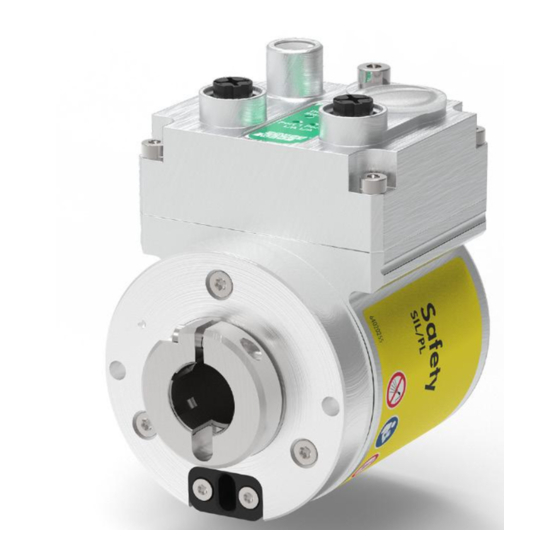
- Page 1 Translation of the original manual Absolute Encoder CD_-582 Safety Manual Pictures show similar items DIN EN 61508: SIL CL2 / SIL CL3 DIN EN ISO 13849: PL d / PL e _Basic safety instructions _Intended use _General functional description _General characteristics _Assembly Safety Manual...
- Page 2 Contents TR-Electronic GmbH D-78647 Trossingen Eglishalde 6 Tel.: (0049) 07425/228-0 Fax: (0049) 07425/228-33 E-mail: info@tr-electronic.de http://www.tr-electronic.de Copyright protection This Manual, including the illustrations contained therein, is subject to copyright protection. Use of this Manual by third parties in contravention of copyright regulations is not permitted.
-
Page 3: Table Of Contents
Contents Contents ........................3 Revision index ......................5 1 General information .................... 6 1.1 Applicability ..........................6 1.2 Other Applicable Documents ....................8 1.3 Abbreviations and terms used ....................8 1.4 General functional description ....................9 2 Basic safety instructions ..................10 2.1 Definition of symbols and notes .................... - Page 4 Contents 9 Accessories ......................28 10 Document Download ..................29 TR-Electronic GmbH 2019, All Rights Reserved Printed in the Federal Republic of Germany Page 4 of 29 TR - ECE - BA - GB - 0142 - 01 06/12/2019...
-
Page 5: Revision Index
Revision index Modification Date Index First release 05/28/19 Draw-wire box added 06/12/19 Printed in the Federal Republic of Germany TR-Electronic GmbH 2019, All Rights Reserved 06/12/2019 TR - ECE - BA - GB - 0142 - 01 Page 5 of 29... -
Page 6: General Information
General information 1 General information This Manual addresses the following topics: ● General functional description ● Basic safety information with declaration of the intended use ● General specifications ● Assembly Since it has a modular structure, this Manual is supplementary to other documentations, such as product data sheets, dimensional drawings, brochures, interface-specific user manuals, etc. - Page 7 The products are labeled with affixed nameplates and are components of a system. Date of manufacture in the format YYYY: Year, MM: Month, DD: Tag Maximum achievable Safety Integrity Level or Performance Level, see Chapter 4.1 on Page 19 Number or identifier of the enclosed pin assignment, see Chapter 10 ->...
-
Page 8: Other Applicable Documents
General information 1.2 Other Applicable Documents ● The responsible organization’s system-specific operating instructions ● This Safety Manual ● Pin assignment ● interface-specific User Manual ● Product data sheet ● optional: User Manual 1.3 Abbreviations and terms used Number of operations that a device will operate prior to 10 % of a sample of those devices would fail to danger Absolute encoder with redundant dual scanning unit, all designs ElectroMagnetic Compatibility... -
Page 9: General Functional Description
1.4 General functional description The rotary measuring system is a safe and absolute multi-turn position measuring system with a safety protocol and a standardized interface that is, however, NOT safety instrumented. The safety measuring system consists of a redundant, dual-channel system in which ●... -
Page 10: Basic Safety Instructions
Basic safety instructions 2 Basic safety instructions 2.1 Definition of symbols and notes means that death or serious injury will occur if the user fails to take the respective precautionary measures. means that death or serious injury can occur if the required precautions are not met. -
Page 11: General Risks When Using The Product
2.2 General risks when using the product The product, hereinafter referred to as measuring system, is manufactured according to state-of-the- art technology and accepted safety rules. Nevertheless, non-intended use can pose a danger to life and limb of the user or third parties, or lead to impairment of the measuring system, or other property values! The measuring system may only be used in technically perfect condition in accordance with its intended use and the instructions set out in the Other Applicable Documents and only by safety-... -
Page 12: Intended Use
Basic safety instructions 2.5 Intended use The safety measuring system can be used for the detection of angular movement and processing of measured data for a downstream safety host in systems in which the safety-related requirements of “Safeguarding travel”, “Safeguarding velocity” or “Safeguarding direction of travel” must be reliably achieved. -
Page 13: Usage In Explosive Atmospheres
2.7 Usage in explosive atmospheres The standard measuring system must be installed in an appropriate explosion protection enclosure as required when used in explosive atmospheres. The products are labeled with an additional marking on the nameplate. The “intended use” as well as any information on the safe usage of the ATEX-compliant measuring system in explosive atmospheres are contained in the User Manual. - Page 14 Basic safety instructions Device type 3 refers to devices with a failure behavior which is dependent on the switching frequency (cycle) and in terms of the draw-wire corresponds to complete extension and retraction of the wire. This fact is expressed by the B10d-value and represents the average number of cycles by which 10 % of the components have failed dangerously.
-
Page 15: Safety Functions Of The Fail-Safe Processing Unit
2.9 Safety functions of the fail-safe processing unit It is mandatory that the safety control, which the measuring system is connected to, executes the safety checks required by the interface-specific User Manual. 2.10 Warranty and liability The “General Terms and Conditions” of TR-Electronic GmbH are generally applicable. They will be submitted to the responsible organization along with the order confirmation or on conclusion of the contract at the latest. -
Page 16: Organizational Measures
Basic safety instructions 2.11 Organizational measures ● The other applicable documents must always be within reach where the measuring system is used. ● In addition to the other applicable documents, generally valid legal and other binding regulations on accident prevention and environmental protection must be observed and communicated. ●... -
Page 17: Safety-Related Instructions
2.13 Safety-related instructions The instructions listed below must be followed to prevent ● destruction, damage and malfunction of the measuring system and downstream electronic devices. – Wiring work may only be carried out and electrical connections only be opened and closed while the system is de-energized. –... - Page 18 Basic safety instructions ● The measuring system contains components and assemblies susceptible to electrical discharge, which can be destroyed if incorrectly handled. – Do not touch the connection contacts of the measuring system with your fingers or apply the relevant ESD protective measures. ●...
-
Page 19: Transport / Storage
3 Transport / Storage ● Shipping information – Do not drop the device or subject it to heavy impacts! The device contains an optical system. – Only use the original packaging. Inappropriate packaging material may cause damage to the unit in transit. ●... -
Page 20: Assembly
Assembly 5 Assembly ● If the safety functions are deactivated because of an unstable shaft drive, there will be the danger of death, serious physical injury and/or damage to property! The system manufacturer must take suitable design measures to ensure that the measuring system is reliably driven by the shaft and firmly attached at any time (fault exclusion). - Page 21 Figure 1: Installing the flange, illustration showing the principle Components: 1: Measuring system 2: Parallel key 3: Centering collar 4: Machine 5: Coupling with groove 6: Drive shaft Printed in the Federal Republic of Germany TR-Electronic GmbH 2019, All Rights Reserved 06/12/2019 TR - ECE - BA - GB - 0142 - 01 Page 21 of 29...
-
Page 22: Blind-Hole Shaft / Hollow Shaft
Assembly 5.2 Blind-hole shaft / hollow shaft 5.2.1 Requirements The following instructions are not exhaustive as the assembly situation may be different for each application. The measuring system must be installed on a grease-free shaft. Axial slipping of the measuring system on the drive shaft must be prevented by fixing the clamping ring in position, see Figure 2. -
Page 23: Potential Equalization - Connection
Components: 1: Measuring system with blind-hole shaft or hollow shaft 2: Alignment pin, provided by customer: Diameter 4 mm with m6 fit Length = distance between reference planes X and Y + deviation C + an immersion depth of 4 ... 5.5 mm 3: Groove insert 4K7, 6 mm deep 4: Groove, according to the article number in the referenced drawing 5: Parallel key: DIN 6885-A 3x3x10... -
Page 24: Replacing The Measuring System
Replacing the measuring system 6 Replacing the measuring system Ensure that you meet the following requirements while replacing the measuring system: ● The new measuring system must have the same article number as the measuring system being replaced; any deviations must be expressly clarified with TR-Electronic. ●... -
Page 25: Checklist, Part 1 Of 2
7 Checklist, Part 1 of 2 We recommend that you print out and work through the checklist for commissioning, replacing the measuring system and when changing the parameterization of a previously accepted system and store it as part of the overall system documentation. Documentation reason Date edited... - Page 26 Checklist, Part 1 of 2 Continued Sub-item Note Reference ● Legacy mode: The preset adjustment function may only be executed when the axis in question is at standstill ● Ensured the preset adjustment ● Interface-specific User Manual Preset adjustment function function can not be triggered ...
-
Page 27: Maintenance
8 Maintenance The measuring system requires no maintenance by the operator. However, if the bearing life of the product is exceeded within a service life of 20 years, the metering system must be taken out of service and sent to the manufacturer. After 20 years of use, the measuring system must be subjected to a proof test. -
Page 28: Accessories
Accessories 9 Accessories Designation Part number Protective cap yellow, M12x1 female thread with O-ring, IP65. 62-000-1664 Suitable for supply voltage connector Protective cap black, M12x1 male thread without O-ring, IP50. 62-000-1344 Suitable for bus and incremental interface connector O-Ring DIN-3771 7x1 NBR 70 SHORE 26-000-332 Suitable for protective cap 62-000-1344 -->... -
Page 29: Document Download
10 Document Download Safety Manual Designation Link Absolute Encoder CD_-582 www.tr-electronic.de/f/TR-ECE-BA-GB-0142 Interface-specific User Manuals Designation Link PROFINET/PROFIsafe www.tr-electronic.de/f/TR-ECE-BA-GB-0139 Pin assignments Link https://www.tr-electronic.com/service/downloads/pin-assignments.html Product data sheets Designation Link Absolute Encoder CD_-582 https://www.tr-electronic.com/s/S020955 EU Declaration of Conformity Link CD_582M +FS02: www.tr-electronic.de/f/TR-ECE-KE-DGB-0354 CD_582M +FS03: www.tr-electronic.de/f/TR-ECE-KE-DGB-0358 Printed in the Federal Republic of Germany ...
Need help?
Do you have a question about the CD_-582 Series and is the answer not in the manual?
Questions and answers