Table of Contents
Advertisement
Quick Links
Advertisement
Table of Contents

Related Manuals for THORLABS InGaAs PDA10CS2


Summary of Contents for THORLABS InGaAs PDA10CS2
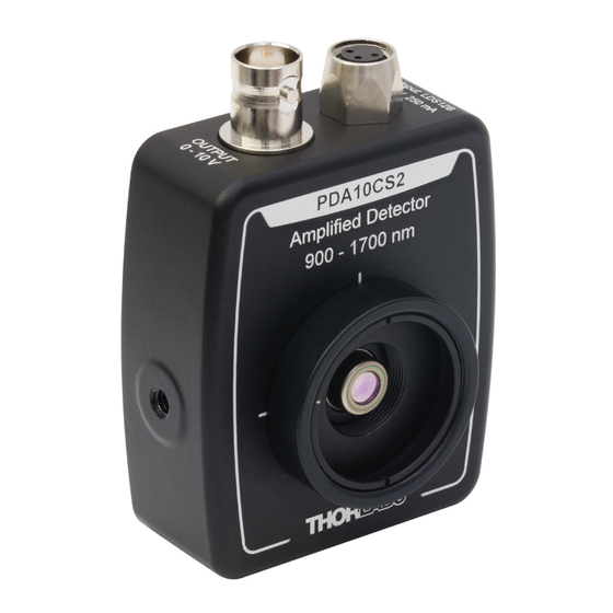
- Page 1 PDA10CS2 InGaAs Switchable Gain Detector User Guide...
-
Page 2: Table Of Contents
4.6. Gain Adjustment ..........5 Chapter 5 Troubleshooting ..........6 Chapter 6 Specifications ............7 6.1. Response Curve ..........9 6.2. Mechanical Drawing ........10 Chapter 7 Certificate of Conformance ......11 Chapter 8 Regulatory ............12 Chapter 9 Thorlabs Worldwide Contacts......13... -
Page 3: Chapter 1 Warning Syzmbol Definitions
InGaAs Switchable Gain Detector Chapter 1: Warning Syzmbol Definitions Chapter 1 Warning Syzmbol Definitions Below is a list of warning symbols you may encounter in this manual or on your device. Symbol Description Direct Current Alternating Current Both Direct and Alternating Current Earth Ground Terminal Protective Conductor Terminal Frame or chassis Terminal... -
Page 4: Chapter 2 Description
A buffered output drives 50 Ω load impedances up to 5 V. The PDA10CS2 housing includes a removable threaded coupler (SM1T1) and retainer ring (SM1RR) that is compatible with any number of Thorlabs 1” threaded accessories. This allows convenient mounting of external optics, light filters, apertures, as well as providing an easy mounting mechanism using Thorlabs’... -
Page 5: Chapter 3 Setup
Attach a 50 Ω coax cable (i.e. RG-58U) to the output of the PDA. When running cable lengths longer than 12" we recommend terminating the opposite end of the coax with a 50 Ω resistor (Thorlabs p/n T4119) for maximum performance. Connect the remaining end to a measurement device such as an oscilloscope or high speed DAQ card. -
Page 6: Chapter 4 Operation
Chapter 4 Operation 4.1. Theory of Operation Thorlabs PDA series are ideal for measuring both pulsed and CW light sources. The PDA10CS2 includes a reverse-biased PIN photo diode, mated to a switchable gain transimpedance amplifier, and packaged in a rugged housing. -
Page 7: Bandwidth And Response
InGaAs Switchable Gain Detector Chapter 4: Operation Material Dark Current Speed Sensitivity Cost Silicon (Si) High 400 - 1000 nm Germanium (Ge) High 900 - 1600 nm Gallium Phosphide (GaP) High 150 - 550 nm Indium Gallium Arsenide High 800 - 1800 nm (InGaAs) Extended Range: Indium High... -
Page 8: Chapter 5 Troubleshooting
InGaAs Switchable Gain Detector Chapter 5: Troubleshooting Chapter 5 Troubleshooting Problem Suggested Solutions Verify that the power is switched on and all connections are secure. Verify the proper terminating resistor is installed if using a Voltage measurement device. There is no signal response. Verify that the optical signal wavelength is within the specified wavelength range. -
Page 9: Chapter 6 Specifications
InGaAs Switchable Gain Detector Chapter 6: Specifications Chapter 6 Specifications All performance specifications are typical, performed at 25 °C ambient temperature, and assume a 50 Ω load, unless stated otherwise. Performance Specifications 0 dB Setting 40 dB Setting Gain (Hi-Z) 1.51 x 10 V/A ±2% Gain (Hi-Z) - Page 10 InGaAs Switchable Gain Detector Chapter 6: Specifications Electrical Specifications Detector InGaAs Active Area Ø1.0 mm (0.8 mm λ Wavelength Range 900 to 1700 nm λ Peak Wavelength 1550 nm (Typ.) ( λ Peak Response 1.05 A/W (Typ.) Amplifier GBP 600 MHz 50 Ω...
-
Page 11: Response Curve
InGaAs Switchable Gain Detector Chapter 6: Specifications 6.1. Response Curve PDA10CS2 Responsivity 1100 1300 1500 1700 Wavelength (nm) Rev D, April 21, 2020 Page 9... -
Page 12: Mechanical Drawing
InGaAs Switchable Gain Detector Chapter 6: Specifications 6.2. Mechanical Drawing Page 10 TTN134846-D02... -
Page 13: Chapter 7 Certificate Of Conformance
InGaAs Switchable Gain Detector Chapter 7: Certificate of Conformance Chapter 7 Certificate of Conformance Rev D, April 21, 2020 Page 11... -
Page 14: Chapter 8 Regulatory
Waste Treatment is Your Own Responsibility If you do not return an “end of life” unit to Thorlabs, you must hand it to a company specialized in waste recovery. Do not dispose of the unit in a litter bin or at a public waste disposal site. -
Page 15: Chapter 9 Thorlabs Worldwide Contacts
InGaAs Switchable Gain Detector Chapter 9: Thorlabs Worldwide Contacts Chapter 9 Thorlabs Worldwide Contacts For technical support or sales inquiries, please visit us at www.thorlabs.com/contact for our most up-to-date contact information. USA, Canada, and South America UK and Ireland Thorlabs, Inc. - Page 16 www.thorlabs.com...
Need help?
Do you have a question about the InGaAs PDA10CS2 and is the answer not in the manual?
Questions and answers