Table of Contents
Advertisement
Quick Links
Advertisement
Chapters
Table of Contents

Subscribe to Our Youtube Channel
Summary of Contents for Metso PZ Series
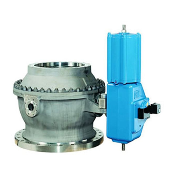
- Page 1 CAPPING VALVE Series PZ Installation, Maintenance and Operating Instructions...
-
Page 2: Table Of Contents
8 PZ 70 en Table of Contents GENERAL ..............3 Scope of the manual ...........3 Valve construction ..........3 Valve markings ............3 Specifications ............3 Valve performance..........4 Valve approval ............5 Recycling and disposal ........5 Safety precautions ..........5 TRANSPORTATION, RECEPTION AND STORAGE ..............5 INSTALLATION AND COMMISSIONING ....5 General .............. -
Page 3: General
8 PZ 70 en GENERAL Scope of the manual This manual provides the essential information needed by users of PZ capping valves. If you require further informa- tion on actuators and instrumentation, see the separate installation, maintenance and operation instructions for the various models. -
Page 4: Valve Performance
90° ball surface damages. rotation as listed: Metso realizes that some mills may require a water wash/ Valve size Adjusted operating time with 6 bar supply spray to the ball surface and others may require a water pressure, B1C actuator bed. -
Page 5: Valve Approval
8 PZ 70 en CAUTION: Do not open the valve during cooking! Valve control must be arranged to ensure that the valve cannot be opened during cooking. Otherwise, personal injury or damage to equipment may result. CAUTION: Beware of hot valve! The valve body may be very hot during use. -
Page 6: Mounting The Valve On The Digester
Metso recom- mends inspecting the valves at least every five (5) years. The inspection and maintenance interval depends on the actual application and process condition. -
Page 7: Bearings (5, 22)
8 PZ 70 en Clean the packing counterbore. Detach the actuator using the extractor, see Push the new packing rings (28) one by one into the Chapter 6. counterbore with the gland (6). Position the cut ends Dismantle the upper body half (1). -
Page 8: Valve Assembly
8 PZ 70 en 4.7.2 Assembly Place e.g. corrugated cardboard in the body to pro- tect the ball during the lifting. Fasten the lifting straps through the flow port. Lift the ball into the lower body half with the stem first through the bonnet opening. -
Page 9: Installing The Actuator
8 PZ 70 en Fig. 13 Measuring "B" Fig. 16 Measuring "A" Feed compressed air into the actuator via the pres- sure regulator, see Fig. 14. Fig. 17 The thickness of the washer Tighten the nuts (18). Fig. - Page 10 8 PZ 70 en Closed position stop screw Open position stop screw Fig. 18 Actuator stop screws Fig. 20 G1 measure Fig. 19 Drawing the marking lines Fig. 21 G2 measure Table 3 G-dimensions Open the valve and adjust the open position stop screw so that the ball and the body flow ports are Valve G1, mm...
-
Page 11: Tools
8 PZ 70 en TOOLS In addition to standard tools, you might need the following special tools, which can be ordered from the manufacturer: Detaching the actuator from the valve - extractor Table 4 Extractors Valve-actuator Extractor PZ 500 - BCP32 8546-5 PZ 600 - BCP32 8546-5... -
Page 12: Exploded View And Parts List
8 PZ 70 en EXPLODED VIEW AND PARTS LIST 35 31 44 (B1C) 42 (BC) 41 (BC, B1C) Item Description Recommended spare part Item Description Recommended spare part Body, upper part Bearing bushing Body, lower part Bearing strip Ball Sealing cord Ball seat Seal strip Bearing bushing... -
Page 13: Rear Tilting Device
8 PZ 70 en REAR TILTING DEVICE Item Description Recommended spare part Support Support bar Cylindrical pin Cylindrical pin Piston rod Bracket Bearing strip V-ring set Casting gland Stud Retainer plate Disc spring set Hexagon nut Cylinder base 072A Sticker "LOCK" Cylinder pipe Cylinder end 074A... -
Page 14: Safety Interlocking (Jammer, Rear Tilting Device)
8 PZ 70 en SAFETY INTERLOCKING (JAMMER, REAR TILTING DEVICE) OPEN AIR SUPPLY IMPORTANT NOTICE! CLOSE "JAMMER" ENERGIZE SOLENOID VALVE 11.A BEFORE ANY VALVE LOCK UNLOCK OPERATION AND KEEP IT ENERGIZED UNTIL VALVE FULLY CLOSED AIR SUPPLY (DURING COOKING PERIOD DE-ENERGIZED). -
Page 15: Dimensions
8 PZ 70 en DIMENSIONS For chip chute mounting A -A N pcs O, M, and N acc. to customer's specification B - B Optional lower flange pattern Valve Main dimensions in mm Pneumatic Weight actuator Type Lower flange* type Depth 490 ≤... -
Page 16: Type Code
Safety equipment versions are specified in Application Bulletins 2611/01/02 (ACC) and 2611/01/03 (Jammer inside the actuator). Metso Flow Control Inc. Europe, Vanha Porvoontie 229, P.O. Box 304, FI-01301 Vantaa, Finland. Tel. +358 20 483 150. Fax +358 20 483 151 North America, 44 Bowditch Drive, P.O.


Need help?
Do you have a question about the PZ Series and is the answer not in the manual?
Questions and answers