Table of Contents
Advertisement
Quick Links
Advertisement
Table of Contents

Related Manuals for Digital Acoustics IP7-FX


Summary of Contents for Digital Acoustics IP7-FX
- Page 1 ™ IP Intercom/Amplifier Reference Manual...
- Page 2 This page left blank...
-
Page 3: Table Of Contents
Table of Contents Overview ..............................1 Specifications ............................2 IP7-FX Layout ............................3 LED Indicators ............................6 Replacing an older Model IP7 ........................7 Connecting Power ............................ 7 PoE ................................7 External Power ............................8 USB Power ..............................8 Audio - Mic and Speaker .......................... 8 Understanding Full Duplex Audio ...................... - Page 4 Physical Dimensions..........................16 Environmental ............................16 Troubleshooting ............................. 17 Reset to Factory Defaults......................... 17 Connecting 1/8” (3.5mm) Audio Plug to the Pluggable connectors ............17 Reducing electrical noise in audio ......................17 Viewing tech support info via the USB port..................... 17 Low Level Flashing Utility .........................
-
Page 5: Overview
• Paging only audio using an analog amplifier which is connected to multiple speakers With this flexible design the IP7-FX can be used in a variety of applications where network-based audio is required. Standard features of the IP7-FX include: •... -
Page 6: Specifications
Specifications Items Specification Network Protocols TCP, UDP, SIP, RTP, ICMP, IGMP Multicast Network Interface 10/100 Ethernet (Auto detection, Auto MDIX) Command protocols Proprietary and Standards Based Audio Resolution G.711 (8-bit PCM and 16-bit uLaw) Audio Sample Rate 8K (Voice band), 22K (Background Music) Audio Frequency 90-4kHz (Voice band), 90-11khz (Background Music) Internal Amplifier... -
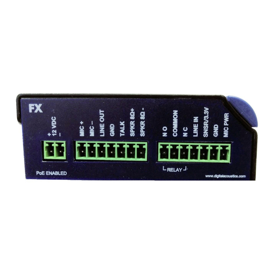
Page 7: Ip7-Fx Layout
IP7-FX Layout Page 3... - Page 8 Will also power the unit for diagnostic purposes. Ext I/O I2C expansion bus interface that can be used for custom applications. Requires custom firmware from Digital Acoustics Ethernet 10/100 10/100 Ethernet network interface. Supports auto negotiation and auto- MDIX. PoE enabled...
- Page 9 J1 Connector Connector Signal Notes 12VDC at 15 watts or 24VDC at 2.5 watts. Overrides PoE power. J1-1 Power + Warning: Connecting power to both the 2.1mm power jack and the J1-1 and J1-2 power connectors at the same time will damage the unit J1-2 Power - J2 Connector...
-
Page 10: Led Indicators
LED Indicators Intercom LEDs There are four LEDs present on the curved bezel on the front of the product. • The blue LED indicates that the IP7-FX has powered up. • The three red LEDs indicate status of the unit. Description... -
Page 11: Replacing An Older Model Ip7
Replacing an older Model IP7 If the IP7-FX is being used to replace an existing an existing IP7- ST/STX, IP7-SS8/SE8 or an IP7-FD, please note the following: • The J3-7 (Case) connector on older models was an extra ground. If replacing an older model with an IP7-FX, any wire connected to J3-7 should be moved to J3-6. -
Page 12: External Power
The 2.1mm Power Jack (center tip positive) and the J1-1(+) / J1-2(-) connectors both accept 12VDC at 1.2 amps or 24VDC at 2.5 amps (With 12VDC, the IP7-FX can supply up to 8 watts to the speaker. With 24VDC, the IP7-FX can supply up to 25 watts to the speaker) •... -
Page 13: Microphones
The Microphone wire must NOT be in the same jacket as the Speaker wire! • Connect the plus and minus leads to the IP7-FX’s J2-1 (Mic+) and J2-2 (Mic-) terminals • Connect the shield to the IP7-FX J2-4 (GND), but do not connect the... -
Page 14: Speakers
An example of a TalkBack Speaker is the Visiton FRS8-8. Speakers The IP7-FX receives audio from the network and plays it on its speaker. It can drive one or more speakers, a self-amplified speaker or an analog amplifier connected to one or more speakers. For best results and to improve performance, connect the speaker or amplifier to the IP7-FX using 18 AWG wire. - Page 15 70V with a 25V distribution line • All speakers must be wired in parallel. • Speakers should be installed within 500 feet (150 meters) of the IP7-FX using 18-gauge wire. For longer runs, increase the wire gauge • Each speaker may be tapped differently •...
-
Page 16: Multiple 8 Ohm Speakers
Multiple 8 Ohm Speakers The IP7-FX is also capable of driving multiple 8 Ohm speakers without 25/70V transformers. • Two 8 Ohm speakers must be wired in series • Four 8 Ohm speakers must be wired in series-parallel Please note the following guidelines: •... -
Page 17: Line Out
18 AWG wire. Dry Contact Relay The Relay connector provides a dry contact output from the IP7-FX suitable for activating equipment such as electronic door strikes, strobe lights or CCTV cameras. Normally Open (N/O) or Normally Closed (N/C) can be chosen. -
Page 18: Snsr/3.3V
Ensure Relay has been properly configured in the Intercom’s Software Configuration program SNSR/3.3V The IP7-FX supports an input sensor that can be used for a variety of applications. The sensor can be defined as Active when closed to ground or Active when open to ground via software. Digital Acoustics’... -
Page 19: Mounting Instructions
• Place the IP7-FX onto the DIN rail by tilting the top of the unit (J1, J2, J3 connectors facing up with Volume buttons and USB-B connector facing forward) back towards the DIN Rail until the IP7-FXs DIN clip catches the top of the rail •... -
Page 20: Configuration
Configuration utility software manuals for instructions on setting the IP address information and optional settings for the IP7-FX. Physical Dimensions The IP7-FX dimensions are as follows: Environmental The IP7-FX is designed to operate indoors or in a weatherproof box that has a NEMA4 or IP66 rating. Page 16... -
Page 21: Troubleshooting
• Attached J3-6 to an earth ground Viewing tech support info via the USB port If requested by Digital Acoustics Support, a USB cable can be attached to the IP7-FX to capture additional information. • Attach a USB cable to the USB-B connector on the unit. -
Page 22: Low Level Flashing Utility
• Press the Enter key • Provide the requested info to Digital Acoustics Tech support Low Level Flashing Utility If a power is removed from the unit while the firmware is being updated from the network, the unit may require a low-level flash. -
Page 23: Regulatory Notices
Cet appareil numérique de la classe A est conforme à la norme NMB-003 du Canada. NOTE: Industry Canada regulations provide that changes or modifications not expressly approved by Digital Acoustics, LLC could void your authority to operate this equipment CE Notice... -
Page 24: Index
Index Aux Power ........ 4 Normally Closed ......5 Normally Open ......5 CASE ........5 Common ........5 PoE .......... 7 Port 2 10/100 ......4 Power ........5 Power - ........5 DIN rail mount ......15 DIN Rail Mounting Clip ....4 Relay connector ....... - Page 25 Notes...
- Page 26 Design and specification are subject to change without notice. Digital Acoustics®, IP7™, ii3™ and TalkMaster™ are trademarks of Digital Acoustics, LLC. I2C is a registered trademark of NXP Semiconductors, Inc. All other marks used are properties of their respective owners.
Need help?
Do you have a question about the IP7-FX and is the answer not in the manual?
Questions and answers