Danfoss AME 110 NL Datasheet
Actuators for modulating control
Hide thumbs
Also See for AME 110 NL:
- Datasheet (8 pages) ,
- Operating manual (24 pages) ,
- Operating manual (8 pages)
Advertisement
Quick Links
Data sheet
Actuators for modulating control
AME 110 NL, AME 120 NL
Description
Ordering
SMT/SI
Supply voltage
Type
(V)
24 AC
Note:
Actuators with 5 m and 10 m cable length are produced on request. Please note this increases lead time.
Spare parts
Length
Type
(m)
5
Cable (24 V)
10
VD.KH.C6.02 © Danfoss 01/2014
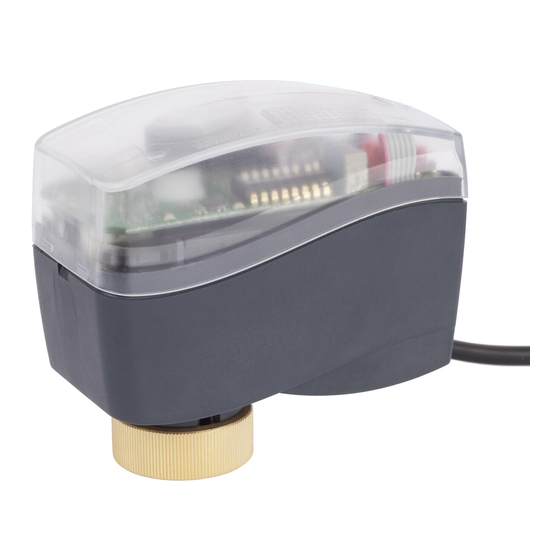
The actuators are used together with
automatically balanced combination valve type
AB-QM for DN 10-32.
The actuator can be used with fan coil units,
induction units, small reheaters, recoolers and
zone applications in which hot/cold water is the
controlled medium.
Main data:
prevents overload of actuator and valve
Speed
Cable length
(s/mm)
(m)
1,5
24
5,0
10
1,5
12
5,0
10
Code No.
082H8052
082H8054
Code No,
082H8057
082H8067
082H8081
082H8077
082H8098
082H8087
082H8059
/
/
082H8079
/
082H8089
1
Advertisement

Related Manuals for Danfoss AME 110 NL


Summary of Contents for Danfoss AME 110 NL
- Page 1 Data sheet Actuators for modulating control AME 110 NL, AME 120 NL Description The actuators are used together with automatically balanced combination valve type AB-QM for DN 10-32. The actuator can be used with fan coil units, induction units, small reheaters, recoolers and zone applications in which hot/cold water is the controlled medium.
-
Page 2: Installation
Data sheet Actuators for modulating control AME 110 NL, AME 120 NL Technical data Type AME 110 NL AME 120 NL 24 AC; +20 to −15% * running standby 50/60 Control input Y Closing force s/mm Relative humidity max. 80 % Max. - Page 3 Data sheet Actuators for modulating control AME 110 NL, AME 120 NL Installation procedure position in stem up position (factory setting). indicator Ensure that the actuator is mounted securely on the valve body 2. Wire the actuator according to the wiring diagram 3.
- Page 4 Data sheet Actuators for modulating control AME 110 NL, AME 120 NL DIP Switch Setting 0-5/5-10 V - Input signal range in (for service purposes only) under the removable cover. sequential mode -5(6) V or 0(4)-10(12) mA. If set to ON position, the U/I - Input signal type selector 5(6)-10 V or 10(12)-20 mA.
- Page 5 Data sheet Actuators for modulating control AME 110 NL, AME 120 NL Manual override (for service purposes only) Caution: Do not manually operate the ② drive if power is connected! ① Do not dismount the actuator from the valve when it is in a...
- Page 6 Data sheet Actuators for modulating control AME 110 NL, AME 120 NL VD.KH.C6.02 © Danfoss 01/2014 SMT/SI...
- Page 7 Data sheet Actuators for modulating control AME 110 NL, AME 120 NL VD.KH.C6.02 © Danfoss 01/2014 SMT/SI...
- Page 8 Data sheet Actuators for modulating control AME 110 NL, AME 120 NL VD.KH.C6.02 Produced by Danfoss A/S © 01/2014...