Advertisement
Available languages
Available languages
Quick Links
V14/2016
SW: HS2117
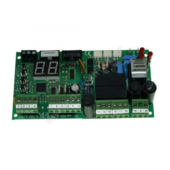
QK-CE220RL4
CONTROL BOARD FOR 1 230V MOTOR
IMPORTANT NOTICE:
This user manual can be used also for the same version of control board
for 110V motors. Item code of the board becomes QK-CE110RL4 and:
- all 230/220V within this manual to be read as 110V
- F1 fuse is 10A
- QK-CE110RL4 control board is equipped with a 110V transformer
E
N
G
L
I
S
H
Advertisement

Subscribe to Our Youtube Channel
Related Manuals for quiko QK-CE220RL4


Summary of Contents for quiko QK-CE220RL4
- Page 1 QK-CE220RL4 CONTROL BOARD FOR 1 230V MOTOR IMPORTANT NOTICE: This user manual can be used also for the same version of control board for 110V motors. Item code of the board becomes QK-CE110RL4 and: - all 230/220V within this manual to be read as 110V...
- Page 2 BOARD LAYOUT BOARD’S COMPONENTS Button A Button B Button C Button D 250 VAC power fuse 5A Resettable fuse 24V 1.6A Resettable fuse 24V 0.6A Ground terminals Primary varistor Secondary varistor 1 to 20 Terminal block pins IMPORTANT RESETTABLE FUSES AFTER SHORT-CIRCUIT TURN OFF THE CONTROL BOARD.
- Page 3 INPUT/OUTPUT CONNECTIONS FUNCTION SUMMARY General Functions Terminal Block Settings Display Report Motor Setting DISPLAY DEFAULT DESCRIPTION Stop. DISPLAY DEFAULT DESCRIPTION DISPLAY DEFAULT DESCRIPTION no = Disabled. External photocell + Pause time. Go = Start N.O. Standard working time Internal photocell. ↓...
- Page 4 TYPICAL INSTALLATION Antenna Internal photocells Flashing lamp Motor INTERNAL OF THE PROPERTY External photocells OPTIONAL QK-AN433_V4 “L” bracket is not available on QK-LUX24E ashing lamp model www.quikoitaly.com 3 of 12...
- Page 5 INPUT/OUTPUT CONNECTIONS INPUT/OUTPUT CONNECTIONS STOP 230 VAC POWER SUPPLY START 230 VAC MOTOR 1 2 3 4 5 6 7 8 9 10 11 12 1 2 3 4 5 6 7 8 9 10 11 12 19 X 20 13 14 15 N.O.
- Page 6 GLOSSARY Stand By The gate is completely closed and the safety devices are unactivated. The control board is ready to start a working cycle. In this state the flashing lamp is off. Opening The gate is opening and the flashing lamp blinks quickly. During pause the motor is stopped and the flashing lamp is on.
- Page 7 MOTOR SETTING The motor works for A1 seconds. After this time the motor starts the slowdown for A2 Standard Working Time seconds. This is for both phases: opening and closing. A1 is settable from 00 to 99 seconds. A2 is settable from 00 to 99 seconds. Slowdown Working Time A3 is the start up time of the motor.
- Page 8 SENSOR OPERATING MODE There are two sensor operating mode: Obstacle Detection and Limit switch. They are described in the table below: Obstacle Detection Limit Switch In this operating mode the motor changes direction. If the direction was In this operating mode the motor finishes the closure, the gate opens completely.
- Page 9 GENERAL FUNCTIONS After the opening the gate waits for F0 seconds before beginning the closing. To disable the automatic closure set Automatic Closure F0 = St Time . To set hold down or keep pressing button C until the display shows It is the motor working time during a pedestrian working cycle.
- Page 10 RADIO FUNCTIONS Keep pressing A or B button until the display shows r0. After a few seconds the control Erasing a remote key board starts scanning for saved codes. Each code showed is a remote key identification number previously saved. To erase a displayed code, hold down button C until display turns off.
- Page 11 TERMINAL BLOCK SETTINGS Each terminal block input is programmable by a configuration parameter. The configuration parameters are configures the terminal block input 1, configures the terminal block input 2 and so E1 = no → DISABLED E1 = Go or oP or CL → ENABLED Input 1 The input 1 is configurable as one of the following functions: Disabled , Start...
- Page 12 COURTESY FUNCTIONS Default Restore To restore the factory default setting, keep pressing button A or B until the display shows d0. After a few seconds the control board shows no. To execute hold down button C until the display shows --. The factory default has been set and the control board state is in stand by state.
- Page 13 Via Seccalegno,19 36040 Sossano (VI) Italia declares under his own responsibility that the product: Control board QK-CE220RL4 complies with the main safety requirements issued by the following directives: Radio Sets - 1999/05/EC ; Low Voltage - 2006/95/EC ; Electromagnetic Compatibility - 2004/108/EC and any revisions thereof, and complies with the provisions that implement said directives in the National Legislation of the Country of destination where the products are to be used.
- Page 17 QK-CE220RL4 SCHEDA DI COMANDO PER 1 MOTORE MONOFASE 230V ac 230 V 433,92 MHz PLUG & MEMORIA PLAY V14/201 SW: HS211...
- Page 18 SCHEMA DELLA CENTRALE COMPONENTI Tasto A Tasto B Tasto C Tasto D Fusibile 250 VAC 5A Fusibile ripristinabile 24V 1.6A Fusibile ripristinabile 24V 0.6A Terminale di terra Connettore elettroserratura Varistore primario Varistore secondario 20 Morsettiera ATTENZIONE FUSIBILE RIPRISTINABILE DOPO UN CORTOCIRCUITO SPEGNERE LA CENTRALE E RIMUOVERE IL CORTOCIRCUITO.
- Page 19 SOMMARIO FUNZIONI IMPOSTAZIONI INGRESSI SEGNALAZIONI IMPOSTAZIONI MOTORE DISPLAY DEFAULT DESCRIZIONE Stop. DISPLAY DEFAULT DESCRIZIONE DISPLAY DEFAULT DESCRIZIONE no = Disabilitato. Fotocellula interna + Tempo di pausa. Go = Start N.A. Fotocellula esterna. Tempo di lavoro normale. ↓ ↑ Per disabilitare tenere oP = Solo Apri N.A.
- Page 20 INSTALLAZIONE TIPO Antenna Lampeggiatore Fotocellule Motore interne INTERNO DELLA PROPRIETÀ Fotocellule esterne ALL’INTERNO DEL CONTENITORE ANTENNA OPTIONAL QK-AN433_V4 Sta a a L non disponibile nella versione QK-LUX24E del lampeggiante www.quikoitaly.com 3 di 12...
- Page 21 COLLEGAMENTI INGRESSI/USCITE ALIMENTAZIONE 230 VAC START STOP MOTORE 230 VAC 19 X 20 1 2 3 4 5 6 7 8 9 10 11 12 1 2 3 4 5 6 7 8 9 10 11 12 13 14 15 N.A.
- Page 22 GLOSSARIO Stand By Il cancello è completamente chiuso e i dispositivi di sicurezza sono disattivati. La centrale di controllo è pronta per iniziare un ciclo di lavoro. In questo stato il lampeggiatore è spento. Apertura Il cancello si sta aprendo e il lampeggiatore lampeggia velocemente. Pausa Durante la Pausa il motore è...
- Page 23 IMPOSTAZIONI MOTORE Il motore lavora per A1 secondi. Dopo questo tempo inizia la fase di rallentamento che Tempo normale dura A2 secondi. Questo avviene sia in apertura che in chiusura. A1 è impostabile da 00 a 99 secondi. A2 è impostabile da 00 a 99 secondi. Tempo rallentamento A3 è...
- Page 24 OPERATIVITÀ DEL SENSORE Ci sono 2 modalità operative RILEVAZIONE OSTACOLI e FINECORSA come descritto nella tabella seguente: RILEVAZIONE OSTACOLI FINE CORSA In questa modalità operativa il motore inverte la direzione. Se stava In questa modalità il sensore finisce la fase chiudendo apre completamente.
- Page 25 FUNZIONI Dopo l'apertura la centrale entra in pausa per F0 secondi dopo di che avvia la fase di chiusura. Tempo Pausa Impostando F0 a St, la centrale al termine della apertura pone il cancello in stato di stop di apertura. Per impostare St premere ripetutamente o mantenere premuto il tasto C finché...
- Page 26 FUNZIONI RADIO Cancellare un Premere ripetutamente o mantenere premuto il tasto A o B finché il display non mostra telecomando Dopo un secondo, la centrale mostra in successione i codici dei telecomandi salvati. Ogni codice è rappresentato da un numero d'identificazione. Per cancellare il codice mostrato mantenere premuto il tasto C finché...
- Page 27 IMPOSTAZIONI INGRESSI ESTERNI Ogni ingresso della morsettiera è programmabile tramite un parametro di configurazione. I parametri di configurazione sono: configura l'ingresso 1, configura l'ingresso 2 e cosi via. E1 = no → DISABILITATO E1 = Go or oP or CL → ABILITATO Ingresso 1 L'ingresso 1 è...
- Page 28 FUNZIONI DI CORTESIA Default Per ripristinare il default di fabbrica: mantenere permuto o premere ripetutamente il tasto A o B finché il display non visualizza d0. Dopo qualche secondo la centrale mostra no. Per impostare il default premere il tasto C finché il display non mostra --. Il default di fabbrica non ha nessun effetto sulla programmazione della radio.
- Page 29 Fabbricante: Quiko Italy Sas Via Seccalegno, 19 36040 Sossano (VI) Italia Quadro di comando QK-CE220RL4 è conforme ai requisiti essenziali di sicurezza delle direttive: Apparecchiature Radio - 1999/5/CE; Bassa Tensione - 2006/95/CE; 2004/108/CE; macchina. Sossano, 10/11/2012 Il Legale Rappresentante Luca Borinato...
- Page 32 Quiko Italy Via Seccalegno, 19 36040 Sossano (VI) - Italy Tel. +39 0444 785513 Fax +39 0444 782371 info@quiko.biz www.quikoitaly.com The Manufacturer can technically improve the quality of its products without any prior notice.
Need help?
Do you have a question about the QK-CE220RL4 and is the answer not in the manual?
Questions and answers