Table of Contents
Advertisement
Available languages
Available languages
21/
9
2
QK-CE220RL4
CONTROL BOARD FOR 1 230V MOTOR
IMPORTANT NOTICE:
This user manual can be used also for the same version of control board
for 110V motors. Item code of the board becomes QK-CE110RL4 and:
- all 230/220V within this manual to be read as 110V
- F1 fuse is 10A
- QK-CE110RL4 control board is equipped with a 110V transformer
E
N
G
L
I
S
H
Advertisement
Table of Contents

Related Manuals for quiko QK-CE220RL4


Summary of Contents for quiko QK-CE220RL4
- Page 1 QK-CE220RL4 CONTROL BOARD FOR 1 230V MOTOR IMPORTANT NOTICE: This user manual can be used also for the same version of control board for 110V motors. Item code of the board becomes QK-CE110RL4 and: - all 230/220V within this manual to be read as 110V...
-
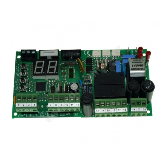
Page 2: Board Layout
BOARD LAYOUT BOARD’S COMPONENTS Button A Button B Button C Button D 250 VAC power fuse 5A Resettable fuse 24V 1.6A Resettable fuse 24V 0.6A Ground terminals Primary varistor Secondary varistor 1 to 20 Terminal block pins IMPORTANT RESETTABLE FUSES AFTER SHORT-CIRCUIT TURN OFF THE CONTROL BOARD. - Page 3 FUNCTIONS SUMMARY Terminal Block Settings Motor Setting General Functions Display Report DISPLAY DESCRIPTION Stop. DISPLAY DEFAULT DESCRIPTION DISPLAY DEFAULT DESCRIPTION Go = Start N.O. (DEFAULT) External (closing) + oP = Open only N.O. Automatic Closure Time. Standard working time Internal (opening) CL = Close only N.O.
-
Page 4: Typical Installation
TYPICAL INSTALLATION Antenna Internal Flashing (opening) photocells lamp Motor INTERNAL OF THE PROPERTY External (closing) photocells INSTALLING RADIO MODULE INSIDE THE FLASHING LAMP INSIDE THE ANTENNA HOUSING OPTIONAL QK-AN433_V4 QK-BRALUX www.quikoitaly.com 3/ 11... - Page 5 INPUT CONNECTIONS 230 VAC MOTOR START STOP 230 VAC POWER SUPPLY 1 2 3 4 5 6 7 8 9 10 11 12 1 2 3 4 5 6 7 8 9 10 11 12 13 14 15 19 X 20 N.O.
- Page 6 GLOSSARY Stand By The gate is completely closed and the safety devices are unactivated. The control board is ready to start a working cycle. In this state the flashing lamp is off. Opening The gate is opening and the flashing lamp blinks quickly. Pause During pause the motor is stopped and the flashing lamp is on.
-
Page 7: Motor Settings
MOTOR SETTINGS Standard Working The motor works for A1 seconds. After this time the motor starts the slowdown for A2 Time seconds. This is for both phases: opening and closing. A1 is settable from 00 to 99 seconds. A2 is settable from 00 to 99 seconds. Slowdown Working Time Start Up Time... -
Page 8: Sensor Operating Mode
SENSOR OPERATING MODE There are two sensor operating mode: Obstacle Detection and Limit switch. They are described in the table below: Obstacle Detection Limit Switch In this operating mode the motor changes direction. If the direction was In this operating mode the motor finishes the closure, the gate opens completely. -
Page 9: General Functions
GENERAL FUNCTIONS Automatic Closure Time After the opening the gate waits for seconds before beginning the closing. To disable the automatic closure set F0 = St . To set hold down or keep pressing button C until the display shows Pedestrian Time A pedestrian command opens the gate for seconds. -
Page 10: Radio Functions
RADIO FUNCTIONS Erasing a remote key Keep pressing A or B button until the display shows r0. After a few seconds the control board starts scanning for saved codes. Each code showed is a remote key identification number previously saved. To erase a displayed code, hold down button C until display turns off. - Page 11 TERMINAL BLOCK SETTINGS Each terminal block is programmable by a configuration parameter. E1 → input 1, E2 → input 2 , E3 → input 3, E4 → input 4, E5 → input 5, E6 → input 6, and E7 → input 7 FUNCTIONS DESCRIPITION TYPE...
- Page 12 TEST Photocells Test → ENABLED → DISABLED t1 = SI t1 = no Each time the gate starts, the control board checks the photocells. If no errors are detected the motor can be started. Vice versa the motor cannot start and the control board display shows 1t. Motor Thermal →...
-
Page 13: Declaration Of Compliance
Via Seccalegno,19 36040 Sossano (VI) Italia declares under his own responsibility that the product: Control board QK-CE220RL4 complies with the main safety requirements issued by the following directives: Radio Sets - 1999/05/EC ; Low Voltage - 2006/95/EC ; Electromagnetic Compatibility - 2004/108/EC and any revisions thereof, and complies with the provisions that implement said directives in the National Legislation of the Country of destination where the products are to be used. - Page 17 Ç QK-CE220RL4 Logique de commande pour un moteur 230V V21/2019 SW: HS2122...
- Page 18 SCHÉMA DE LA CENTRALE PLACER LE MODULE À L’INTÉRIEUR DU CLIGNOTANT OU DANS LE BOÎTIER DE L'ANTENNE POUR AUGMENTER LA PORTÉE DU COMPOSANTES SIGNAL RADIO Bouton A RADIO Bouton B Bouton C Bouton D Fusible 250VAC 5A Resettable fuse 24V 1.6A Resettable fuse 24V 0.6A Bornes de masse Connecteur electro-serrure...
- Page 19 SOMMAIRE DES FONCTIONS Réglage moteur A Réglage du bornier Fonctions générales Signalisations AFFICHAGE DÉSCRIPTION AFFICHAGE DÉFAUT DÉSCRIPTION Stop. AFFICHAGE DÉFAUT DÉSCRIPTION no = Désactivé. Photocellule externe + Temps de travail standard. Temps de fermeture Go = Start N.O. Photocellule interne. automatique oP = Ouvre seulement N.O.
- Page 20 INSTALLATION TYPIQUE Antenne Lampe clignotante Photocellules internes Moteur INTÉRIEUR DE LA PROPRIÉTÉ Photocellules externes INSTALLATION DE LA RADIO L'INTÉRIEUR DE L'ÉTUIT DE L'ANTENNE L'INTÉRIEUR DE LA LAMPE CLIGNOTANTE QK-ANA433_V4 OPTIONNEL OPTIONNEL QK-BRALUX www.quikoitaly.com 3/ 11...
- Page 21 CONNECTIONS DES ENTRÉES / SORTIES STOP START MOTEUR 230 VAC ALIMENTATION 230 VCA 1 2 3 4 5 6 7 8 9 10 11 12 1 2 3 4 5 6 7 8 9 10 11 12 13 14 15 19 X 20 N.O.
- Page 22 GLOSSAIRE Stand By Le portail est complètement fermé et les dispositifs de sécurité sont désactivés. La centrale de commande est prête à commencer un cycle de travail. Dans cet état la lampe clignotante est éteinte. Ouverture Le portail est entrain de s'ouvrir et la lampe clignotante clignote rapidement. Pause Pendant la pause le moteur est arrêté...
- Page 23 PARAMÈTRES DU MOTEUR Temps de travail Le moteur fonctionne pour A1 secondes. Après ce temps, le moteur commence à ralentir standard pour A2. Ceci est valable pour les deux phases: Ouverture et fermeture. A1 est réglable de 00 à 99 secondes. A2 est réglable de 00 à...
- Page 24 MODE OPÉRATOIRE DU CAPTEUR Il y a deux modes opératoires du capteur: Détection d’obstacles et fin de course. Ils sont décrits dans le tableau suivant: Détection d’obstacles Fin de course Dans ce mode opératoire le moteur change de sens de marche. Si le sens Dans ce mode opératoire le moteur termine la était celui de la fermeture, le portail s'ouvre complètement.
-
Page 25: Fonctions Générales
FONCTIONS GÉNÉRALES Temps de fermeture Après l'ouverture la centrale attend secondes avant de fermer. Pour désactiver la fermeture automatique automatique régler . Pour régler maintenr appuyé le bouton C jusqu'à ce que l'afficheur indique .Lorsque F0 = St F0 = le portail s'arrête après l'ouverture. -
Page 26: Fonctions Radio
FONCTIONS RADIO Effacer le code d'un Maintenir appuyé le bouton A ou B jusqu'à ce que l'afficheur indique r0. Après quelques secondes la centrale émetteur montre un balayage des codes présents dans la mémoire. Chaque code montré est un nombre identificatif du code d'un émetteur sauvgardé... - Page 27 CONFIGURATION DU BORNIER Each terminal block is programmable by a configuration parameter. E1 → input 1, E2 → input 2 , E3 → input 3, E4 → input 4, E5 → input 5, E6 → input 6, and E7 → input 7. FUNCTIONS DESCRIPITION TYPE...
- Page 28 TEST Test Photocellules → DÉSACTIVÉ → ACTIVÉ t1 = SI t1 = no Avant toute manoeuvre, la centrale contrôle la présence des photocellules. Si aucune erreur n'est relevée, les moteurs peuvent être démarrés. Autrement les moteurs ne peuvent pas démarrer et l'afficheur indique 1t. Test thérmique des →...
- Page 29 Via Seccalegno,19 36040 Sossano (VI) Italia declares under his own responsibility that the product: Control board QK-CE220RL4 complies with the main safety requirements issued by the following directives: Radio Sets - 1999/05/EC ; Low Voltage - 2006/95/EC ; Electromagnetic Compatibility - 2004/108/EC and any revisions thereof, and complies with the provisions that implement said directives in the National Legislation of the Country of destination where the products are to be used.
Need help?
Do you have a question about the QK-CE220RL4 and is the answer not in the manual?
Questions and answers