Sungrow SG1100UD Series Operation And Maintenance Manual
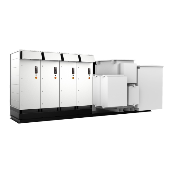
1+x modular inverter
Hide thumbs
Also See for SG1100UD Series:
- System manual (116 pages) ,
- User manual (18 pages) ,
- User manual (136 pages)

Related Manuals for Sungrow SG1100UD Series


Summary of Contents for Sungrow SG1100UD Series
- Page 1 Operation and Maintenance Guide 1+X Modular Inverter SG1100UD Series SG1100UD Series1+X Modular InverterOperation and Maintenance Guide1+X Modular Inverter Operation and Maintenance Guide- US-SEN-Ver13-202312 1+X Modular Inverter Operation and Maintenance Guide-US-SEN-Ver13-202312...
-
Page 3: All Rights Reserved
Software Licenses • It is prohibited to use data contained in firmware or software developed by SUNGROW, in part or in full, for commercial purposes by any means. • It is prohibited to perform reverse engineering, cracking, or any other operations that... -
Page 5: Table Of Contents
Contents All Rights Reserved .....................I 1 About This Manual ...................1 1.1 Target Group ....................1 1.2 How to Use This Manual .................1 1.3 Symbol Explanations ..................1 2 Safety Instructions ....................3 2.1 Operation.......................4 2.2 Electrical Connection ..................4 2.3 Hoisting and Transportation................5 2.4 Operation and Maintenance ................6 2.5 Disposal ......................7 2.6 Symbol on Products..................8 3 System Description... - Page 6 6.1 Inverter Troubleshooting ................16 6.1.1 Viewing Fault/Alarm Information............16 6.1.2 Check Method ..................16 6.2 Other Faults ....................28 7 Routine Maintenance ..................30 7.1 Safety Instructions ..................30 7.2 Maintenance Period..................32 7.2.1 Maintenance (Once Every Three Years)..........32 7.2.2 Maintenance (Every two years) ............33 7.2.3 Maintenance (Once A Year) ..............34 7.2.4 Maintenance (Every half a year to once a year) ........35 8 Maintaining Inverter Units ................37...
-
Page 7: About This Manual
About This Manual This manual describes the methods for stopping, troubleshooting, and daily maintenance of the 1+X modular inverter. Target Group This manual is intended for professional technicians who are responsible for the installation, operation, and maintenance of MV grid-connected inverters. The professional technician is required to meet the following requirements: •... - Page 8 1 About This Manual Operation and Maintenance Guide DANGER indicates high-risk potential hazards that, if not avoided, may lead to death or serious injury. WARNING indicates moderate-risk potential hazards that, if not avoided, may lead to death or serious injury. CAUTION indicates a slightly hazardous situation which, if not avoided, may result in minor or moderate injury.
-
Page 9: Safety Instructions
Perform operations considering ac- tual onsite conditions. • SUNGROW shall not be held liable for any damage caused by violation of gen- eral safety operation requirements, general safety standards, or any safety in- struction in this manual. -
Page 10: Operation
2 Safety Instructions Operation and Maintenance Guide Operation When the product is working, • It is strictly forbidden to touch the live parts of the product. Otherwise, an elec- tric shock may occur. • It is strictly prohibited to disassemble any parts of the product. Otherwise, an electric shock may occur. -
Page 11: Hoisting And Transportation
Operation and Maintenance Guide 2 Safety Instructions Damage to the device caused by incorrect wiring is not covered by the warranty. • Electrical connection must be performed by professional personnel who wear personal protective equipment. • All cables used in the PV generation system must be firmly attached, properly insulated, and adequately dimensioned. -
Page 12: Operation And Maintenance
2 Safety Instructions Operation and Maintenance Guide Improper hoisting may cause personal injury! • It is strictly prohibited to stand within 5m - 10m outside the operating area (i.e., under the boom and the hoisted machine) to avoid casualties. • The product must be hoisted and moved by professional personnel. -
Page 13: Disposal
SUNGROW. To avoid the risk of electric shock, do not perform any other maintenance opera- tions beyond those described in this manual. If necessary, contact SUNGROW for maintenance. Otherwise, the losses caused are not covered by the warranty. If work is carried out while the device is live, insulation protection is necessary and at least two personnel should be present at the site at the same time. -
Page 14: Symbol On Products
2 Safety Instructions Operation and Maintenance Guide Symbol on Products Explanation Marks High voltage inside! Risk of electric shock by touching it! The temperature here is beyond the acceptable range for the human body, please do not touch it arbitrarily to avoid personal injury. -
Page 15: System Description
System Description Product Introduction In large and medium-sized utility power plant systems, the MV grid-connected inverter, which contains multiple PV inverter units, transformers, and other equipment, provides a sound solution to convert the DC power generated by PV arrays into AC power, and feed it into the grid. - Page 16 3 System Description Operation and Maintenance Guide * The figure is for reference only. And the actual product received shall prevail. Description Name Disconnect it before maintenance and repair. Maintenance switch QS2 Control the on/off of the DC side circuits of the DC load switch QS1 inverter.
-
Page 17: Powering Up And Powering Down
Powering up and Powering down Safety Instructions High voltage! Electric shock! • Wear proper protection equipment before all operations on the device. • Do not touch the live terminals or conductors. • Respect all safety instructions attached on the device and described in this manual. -
Page 18: Powering Up Steps
4 Powering up and Powering down Operation and Maintenance Guide Powering Up Steps Step 1 Turn on the maintenance switch QS2 of all inverter units and the external power supply equipment switch (which is, the QS4 switch inside the power distribution cabinet). Then, close the door. -
Page 19: Unplanned (Emergency) Powering Down
Operation and Maintenance Guide 4 Powering up and Powering down 4.3.2 Unplanned (Emergency) Powering Down Step 1 Press the emergency stop button on the DC side. Upon pressing the emergency stop button, only the AC circuit breaker and DC load switch will open. -
Page 20: Web Interface
SG-xxx (xxx represents the device SN), and enter the password. The password is ESPWifi@123. Step 2 Open a browser on the mobile phone and enter the address (11.11.11.1) or domain (sungrow. net) to access the WEB interface. - - End Login Steps Step 1 Enter the server address to enter the homepage as a visitor by default. -
Page 21: Boot/Shutdown
Operation and Maintenance Guide 5 WEB Interface Step 4 Enter the password and click Login to enter the interface as a general user. PC password: pw8888. After the initial login, please change the password in a timely manner to avoid pop-up modify password prompts. -
Page 22: Troubleshooting
Whether the emergency stop button is pressed • Whether the inverter limits the output of active power If the problem still persists or there are any other questions, please contact SUNGROW. It would be helpful if the following information is provided during a call: •... - Page 23 Operation and Maintenance Guide 6 Troubleshooting Fault Name Fault Cause Fault Level Corrective Method 1. Check whether a short circuit occurs on the AC or DC sides of The drive board the inverter. generates a fault IGBT Module 2. Check the grid for any Important signal or a hard- fault...
- Page 24 6 Troubleshooting Operation and Maintenance Guide Fault Name Fault Cause Fault Level Corrective Method 1. Check whether the grid vol- tage is normal. 2. Check whether the control fan is normal. The temperature Control cabinet 3. Check the AC filter system. inside the control Important temperature...
- Page 25 Operation and Maintenance Guide 6 Troubleshooting Fault Name Fault Cause Fault Level Corrective Method 1. Check whether the ambient temperature is normal; Use a thermometer to check whether the current ambient temperature is within the tem- perature range advertised by the If the temperature inverter.
- Page 26 6 Troubleshooting Operation and Maintenance Guide Fault Name Fault Cause Fault Level Corrective Method 1 Check whether the protection parameters on the interface meet the grid standards of the lo- cation where the inverter is The grid fre- Frequency fault Important installed.
- Page 27 Operation and Maintenance Guide 6 Troubleshooting Fault Name Fault Cause Fault Level Corrective Method Check whether the power grid is The inverter fails Important abnormal, such as harmonics Soft start fault to start. and voltage balance. Check the status indicator of the SPD.
- Page 28 6 Troubleshooting Operation and Maintenance Guide Fault Name Fault Cause Fault Level Corrective Method Disconnect the DC switch of the inverter and check whether the open-circuit voltage of the PV ar- rays is normal; If not, the PV ar- ray configuration may be faulty. The DC side vol- 2.
- Page 29 Operation and Maintenance Guide 6 Troubleshooting Fault Name Fault Cause Fault Level Corrective Method 1. Check the air inlet. 2. Check whether the air outlet The temperature of the inverter is blocked. Re- Module over- of modules inside place the air filter screen if Important temperature the inverter is ex-...
- Page 30 AC cabinet. Clean it if necessary. Check whether the DC fuse is The fuse on the blown. DC fuse Secondary DC side of the in- anomaly If so, please contact SUNGROW verter fails. to replace the fuse.
- Page 31 2. Check the communication terminal of the meter is loose. Check whether the DC fuse is The fuse on the blown. Secondary DC fuse fault DC side of the in- If so, please contact SUNGROW verter fails. to replace the fuse.
- Page 32 HVRT or LVRT. voltage. If the fault/alarm cannot be cleared following the above corrective methods and still persists, please contact SUNGROW directly. Fault Name Fault Cause Fault Level Corrective Method The AC switch is...
- Page 33 Fault Level Corrective Method The addresses of the inver- Machine code re- Please contact Important ter units inside the inverter petition fault SUNGROW. are the same. Temperature and The communication of the humidity board Please contact Secondary temperature and humidity communication SUNGROW.
-
Page 34: Other Faults
If the fault is not caused by the fore- going reasons and still persists, please contact SUNGROW as soon as possible. 1. Refresh the Web page manually. 2. Restart or replace the mobile de-... - Page 35 Method”. If the fault is not caused by the fore- going reasons and still persists, please contact SUNGROW as soon as possible. 1. Export data in batches multiple The amount of data ex- Fail to export measur- times.
-
Page 36: Routine Maintenance
Routine Maintenance Safety Instructions Risk of inverter damage or personal injury due to incorrect service! • Disconnect the switches between the product and all power supplies before maintenance. • After the inverter is powered off for 5 minutes, measure the voltage and current with measuring equipment. - Page 37 To avoid the risk of electric shock, do not perform any other maintenance opera- tions beyond those described in this manual. If necessary, contact SUNGROW for maintenance. Otherwise, the losses caused are not covered by the warranty.
-
Page 38: Maintenance Period
7 Routine Maintenance Operation and Maintenance Guide Maintenance Period 7.2.1 Maintenance (Once Every Three Years) Item Check method • Oil thermometer: Alarm temperature and tripping temperature. • Pressure relief valve: Check whether the pressure re- lief valve is in good contact. Monitoring and protective equipment of the transformer •... -
Page 39: Maintenance (Every Two Years)
Operation and Maintenance Guide 7 Routine Maintenance 7.2.2 Maintenance (Every two years) Item Check method Check the following items, and correct immedi- ately those failing to meet the relevant requirements: • Check whether there is any damage or deforma- tion of the inverter and internal equipment. •... -
Page 40: Maintenance (Once A Year)
7 Routine Maintenance Operation and Maintenance Guide 7.2.3 Maintenance (Once A Year) Item Check method Check the following items, and correct immediately those fail- ing to meet relevant requirements: • Check whether there are flammable objects on the top of the inverter. -
Page 41: Maintenance (Every Half A Year To Once A Year)
Operation and Maintenance Guide 7 Routine Maintenance Item Check method Check the following items, and correct immediately those fail- ing to meet relevant requirements: • Check whether there are flammable objects on the top of the inverter. • Check whether the welding points between the inverter and foundation steel plate are firm and if there is corrosion. - Page 42 7 Routine Maintenance Operation and Maintenance Guide Item Check method Check the temperature of the heat sink and the amount of dust accumulated. Clean heat-dissipation modules with a vacuum cleaner if necessary. Air inlet and outlet For maintenance of air inlet and outlet, please refer to "9.1 Clean Top Air Outlet of Inverter Unit"...
-
Page 43: Maintaining Inverter Units
Maintaining Inverter Units If some inverter units are faulty and need to be repaired during operation, replace the faulty unit following the steps in this section. Installation Tools Installation tools include but are not limited to the following recommended ones. Other auxili- ary tools on site can also be used as needed. -
Page 44: Removing Dc Side Cables
8 Maintaining Inverter Units Operation and Maintenance Guide Removing DC Side Cables • After the whole system is stopped, wait at least 5 minutes and confirm that the product is completely voltage-free inside. Then, you may proceed with the maintenance. •... -
Page 45: Remove Ac Side Cables
Operation and Maintenance Guide 8 Maintaining Inverter Units - - End Remove AC Side Cables 1+X modular inverter is composed of multiple PV inverter units. Take SG4400UD as an ex- ample, the AC side layout of #1/#4 inverter unit and #2/#3 inverter unit is different. Pay atten- tion to distinguish inverter units when removing the AC side cables. - Page 46 8 Maintaining Inverter Units Operation and Maintenance Guide Step 2 Unscrew the M10 bolt assembly and remove the AC wiring copper bar from front to back. Step 3 Tear off all silicone pads marked in the figure below, then unscrew the M5 flange nut, and re- move the AC epoxy plate, the PC plate, and the hose of cables between inverter units.
-
Page 47: Removing #2/#3 Inverter Unit
Operation and Maintenance Guide 8 Maintaining Inverter Units figure 8-2 #4 Inverter Unit Step 4 Unplug the cables between inverter units and cables of the self-constructed grid (optional). Insulate the cables between inverter units and plug them into the bottom junction box. The components shown in the figure are for reference only. - Page 48 8 Maintaining Inverter Units Operation and Maintenance Guide Step 2 Unscrew the M10 bolt assembly and remove the AC wiring copper bar from front to back. Step 3 Tear off all silicone pads marked in the figure below, then unscrew the M5 flange nut, and re- move the AC epoxy plate and the PC plate.
-
Page 49: Remove Connections Between Inverter Units
Operation and Maintenance Guide 8 Maintaining Inverter Units Remove Connections Between Inverter Units Step 1 Unscrew the M8 bolts at the bottom of the AC and DC sides of the inverter unit. Remove the connecting pieces on the inverter unit to be maintained. Step 2 Unscrew the M6 cross recessed hexagon bolt assembly and remove the DC and AC cable sealing plates on the bottom. - Page 50 8 Maintaining Inverter Units Operation and Maintenance Guide Step 6 Hoist the inverter unit out of the cabinet through the top four lifting auxiliary parts. Use four flexible synthetic slings, with a length of at least 3.2 m and lifting capacity of over 2 tons, to lift the inverter unit.
- Page 51 Operation and Maintenance Guide 8 Maintaining Inverter Units During installation, to ensure the sealing effectiveness, apply adhesive around all silicone pads to seal them off.
-
Page 52: Common Maintenance Items
Common Maintenance Items • Wait 5 minutes after the system is powered off, and then you can proceed with maintenance and overhaul. • All component maintenance operations must be carried out while the product is in a power off state. Ensure that a functional spare device of the same model is available before repla- cing a damaged component. -
Page 53: Clean Bottom Air Outlet Of Inverter Unit
Operation and Maintenance Guide 9 Common Maintenance Items Step 3 Install the filter in reverse steps. The M5 fixing screws are used for transport and do not need to be fit back. - - End Clean Bottom Air Outlet of Inverter Unit It is expected to be finished in 5 minutes. -
Page 54: Replace Igbt Module
9 Common Maintenance Items Operation and Maintenance Guide Step 2 Remove the old fuses and insert the new fuses. Step 3 Close the fuse holder in the AC side SPD. - - End Replace IGBT Module Use a multimeter to test the DC bus fuse on the AC side. Make sure the voltage measurement is lower than the safe voltage for humans, and then you may pro- ceed with module maintenance. -
Page 55: Replace Fans
Operation and Maintenance Guide 9 Common Maintenance Items Step 4 Fit the 18 bolts used for connecting the capacitance pool bus and the IGBT module. Step 5 On the AC side, disconnect and remove the drive and grounding cables connected to the module, and take out the IGBT module. -
Page 56: Appearance Repair
9 Common Maintenance Items Operation and Maintenance Guide Step 2 Remove the M5 bolts from the top door on the AC cabinet and open the fan cabinet door. Step 3 Open the fan cable duct and disconnect its wiring terminals. Step 4 Remove the bolted connections between the fan fixing plate and the bottom platform. -
Page 57: Erasable Traces
Operation and Maintenance Guide 9 Common Maintenance Items 9.6.1 Erasable Traces Tools Name Source Cleaning cloth Beyond the scope of supply Water Alcohol or other non-corrosive detergents Step 1 Wet the cleaning cloth (or other scrubbing tools) with water, and scrub the dirty parts on the surface. -
Page 58: Broken Primer
9 Common Maintenance Items Operation and Maintenance Guide - - End 9.6.3 Broken Primer Tools Name Source Abrasive paper Cleaning cloth Water Beyond the scope of supply Alcohol Zinc primer Brush RAL7035 oil paint Step 1 Polish the damaged parts with abrasive paper to remove rust and other burrs for a smooth surface. -
Page 59: Maintenance Of Other Components
* If the DC input of the inverter is equipped with MPLC, use M8×30 and M10×30 bolts. Maintenance of Other Components The maintenance and estimated time required for other components are shown in the table below. For specific maintenance operations, please contact SUNGROW. Time (minutes) Name... - Page 60 9 Common Maintenance Items Operation and Maintenance Guide Time (minutes) Name Balance board Standby power board LED screen DC-side Current sensor AC-side Current sensor Three-phase transformer Aluminum-shell resistor * The maintenance time listed in the table is for reference only. The maintenance work should be conducted based on the on-site conditions.
-
Page 61: Appendix
• The customer shall give SUNGROW a reasonable period to repair the faulty device. Exclusion of Liability In the following circumstances, SUNGROW has the right to refuse to honor the quality guarantee: • The free warranty period for the whole machine/components has expired. - Page 62 10 Appendix Operation and Maintenance Guide • Serial number of the device • Fault code/name • Brief description of the problem For detailed contact information, please visit: https://en.sungrowpower.com/contactUS...
Need help?
Do you have a question about the SG1100UD Series and is the answer not in the manual?
Questions and answers