
Subscribe to Our Youtube Channel
Related Manuals for OT Bioelettronica EMG-USB2


Summary of Contents for OT Bioelettronica EMG-USB2
- Page 1 User manual v 2.0 EMG-USB2 Multichannel Bioelectrical Signal Amplifier Read this manual carefully before using the EMG-USB2 amplifier.
- Page 2 EMG-USB2 User manual v.2.0 pag. 2/31...
-
Page 3: Table Of Contents
Contraindications .................... pag. 6 Side effects ....................pag. 6 4. SAFETY CAUTIONS AND OTHER WARNINGS ............pag. 7 5. SYMBOLS USED ON EMG-USB2 AND IN THE USER MANUAL ......pag. 9 6. TECHNICAL SPECIFICATIONS ................pag. 10 7. DETAILED DESCRIPTION ..................pag. 12 FRONT PANEL ..................... - Page 4 EMG-USB2 User manual v.2.0 pag. 4/31...
-
Page 5: General Description
EMG & MOTOR UNIT LABORATORY of Aalborg University. The EMG-USB2 is a modular system. It can amplify from 16 up to 256 bioelectrical channels, in modules of 16 channels per board installed. The number of amplifier boards installed in the system determines the total number of channels. -
Page 6: Emg-Usb2 Kit Content
1 EMG-USB2 user manual. 3. END USER EMG-USB2 multichannel amplifier allows invasive and non invasive recording of biopotentials (iEMG, sEMG, EEG, ECG) detected by superficial and intramuscular electrode. In case of sEMG, EEG and ECG recordings the end user must be familiar with the technique and received a proper training in EMG or EEG or ECG detection and interpretation. -
Page 7: Safety Cautions And Other Warnings
Contact the manufacturer immediately if extraneous materials permeate into the device (liquids, powders, etc.). In case of hard shocks suffered by the EMG-USB2 (like a drop to the floor, etc.), verify that no crack or any other kind of damage of the box resulted from the shock. - Page 8 EMG-USB2 is not designed to be portable equipment. Should it be necessary to move the EMG- USB2 electromyograph, it must be properly packaged to avoid typical vibrations and shocks arising from transportations.
-
Page 9: Symbols Used On Emg-Usb2 And In The User Manual
EMG-USB2 User manual v.2.0 5. SYMBOLS USED ON EMG-USB2 AND IN THE USER MANUAL Class BF for circuitry applied to patient. Read carefully the instruction remarks before use. Dangerous voltage level, power line voltage. Multifunction keys to select the parameter to be modified. -
Page 10: Technical Specifications
6. TECHNICAL SPECIFICATIONS EMG-USB2 is an optically and galvanically insulated device designed to guarantee a high safety level for the patient and the operator in all operating conditions. The optical and galvanic insulation separates the circuitry connected to the patient from the circuitry connected to external non-medical devices, such as the PC used for data acquisition and user interface. - Page 11 EMG-USB2 User manual v.2.0 EMG-USB2 technical specifications are shown in TAB. 2. Amplification channels (IN1÷4 and MULTIPLE IN 1÷3) Selectable gain OFF, 100, 200, 500, 1000, 2000, 5000, 10000 V/V High pass filter: 3, 10, 100, 200 Hz Selectable bandwidth...
-
Page 12: Detailed Description
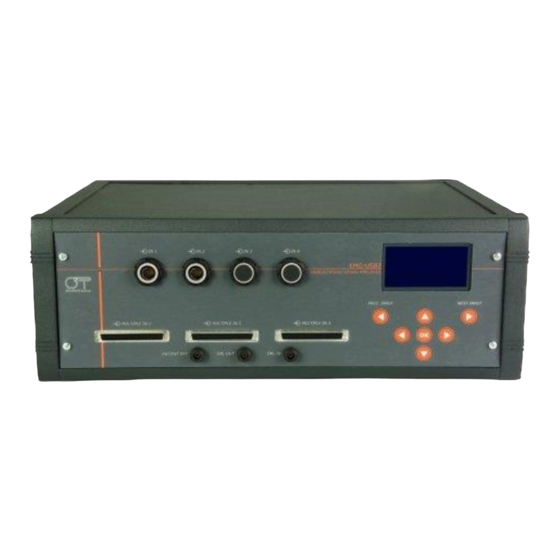
EMG-USB2 User manual v.2.0 7. DETAILED DESCRIPTION FRONT PANEL FIG. 1 shows controls, indicators and connectors present on the front panel of the EMG-USB2 and described in the following sections. connectors Multiple IN connectors Liquid crystal display IN 1 IN 2... -
Page 13: Multiple Input Connectors: Multiple In 1÷3
(Mode: Float. Monop.) the DRL IN is also one of the two inputs of all EMG-USB2 first stages. Thus, when the amplifier is in this mode, it is mandatory to connect the patient to this input. A ground strip must be wet with water to ensure a good electric contact with the patient and has to be connected to a point on the patient’s body... -
Page 14: Drl Out Connector
Liquid crystal display and keypad The liquid crystal display is turned on when the EMG-USB2 amplifier is switched on. After an introducing screen-shot, the EMG-USB2 settings are presented as shown in FIG. 2. IN 1 MENU MODE: Chained Diff. -
Page 15: Rear Panel
DANGER: the use of extension cords, multiple sockets or adapters can impair the performance of the EMG-USB2. Connection to sockets without proper grounding (e.g. lacking the “earth” conductor) or with bad quality grounding can impair the performance of the EMG-USB2 and cause a potential risk for the patient and the operator. -
Page 16: Fuse Box
EMG-USB2 from the slits on the bottom panel and exits through the fan. The following cautions must be observed: Ensure to leave at least 8 cm of clear space behind the EMG-USB2 to ensure a suitable airflow. Do not obstruct the slits on the bottom panel. -
Page 17: Usb Connector
The sixteen auxiliary inputs work even if no other inputs of the front panel are used. Thus, the EMG-USB2 can be used as an sixteen channels USB acquisition board. To properly set and acquire these channels refer to the OT BioLab user manual. -
Page 18: Use Of Emg-Usb2
8. USE OF EMG-USB2 EMG-USB2 CONFIGURATION The embedded keypad and the display on the front panel of EMG-USB2, allow the operator to change the settings of the amplifier as explained in the following instructions: Using PREV. INPUT and NEXT INPUT keys it is possible to browse the inputs menu. - Page 19 EMG-USB2 User manual v.2.0 Parameter Available options Description It is a single differential mode. Each channel amplify the difference between a subsequent signals of each input . The last channel of each input is obtained as difference between the last signal of the same input and the first signal of the subsequent input.
-
Page 20: Amplification Gain
EMG-USB2 User manual v.2.0 Amplification Gain The amplification gain for each input can be set by the user. Indication of the gain settings are displayed at the second line of every input menu. The gain by default can be different for each amplifier input. -
Page 21: Analog Out Setting
TAB. 5: Selectable filters description Analog out setting The EMG-USB2 features an analog output (refer to the details of the rear panel of the instrument) where can be sent one of the signals filtered and amplified by the available channels. This signal is internally sampled at 10240 Hz and converted in digital form, cross the insulation barrier and then is re-converted in an analog signal. -
Page 22: Backlight Management
Firmware upgrade Using OT BioLab it is possible to upgrade the instrument firmware. What can be upgraded using this procedure is the firmware loaded in the microcontroller that manage the EMG-USB2 user interface (display and keypad) and amplification parameters. To upgrade the firmware it is necessary obtain a valid upgrade file and transfer it using a special feature of OT BioLab. -
Page 23: Connection Setup
Make sure that the EMG-USB2 power on switch is set in “O” position. Connect the USB port, placed on the EMG-USB2 rear panel, to one of the PC USB port by means of an A-B USB cable. -
Page 24: Patient Connection
(e.g. the ankle or the wrist, FIG. 6). REMARK: the lack of this connection prevents the correct acquisition of the EMG signal. Figures 6, 7, 8 and 9 show some connections example to acquirebioelectrical signals in different modalities available using EMG-USB2. EMG-USB2 Patient... - Page 25 EMG-USB2 User manual v.2.0 EMG-USB2 Left Patient wrist Right Patient wrist Patient reference strip Cables PATIENT REF Adapter DRL OUT DRL IN FIG. 7: Patient connection diagram for signal acquisition in floating monopolar modality (Mode: Float. Monop.). EMG-USB2 Left Patient...
- Page 26 EMG-USB2 User manual v.2.0 EMG-USB2 Patient wrist Patient reference strip Cables PATIENT REF Bipolar Adapter FIG. 9: Patient connection diagram for signal acquisition in bipolar modality (Mode: Bipolar). pag. 26/31...
-
Page 27: Troubleshooting
EMG-USB2 User manual v.2.0 9. TROUBLESHOOTING This section describes the most common problems that may be found by EMG-USB2 users, with some suggestions to solve them. For problems not described in this section contact the Technical Support Service of OT Bioelettronica. -
Page 28: Emg-Usb2 Maintenance And Storage
Atmospheric pressure: from 700 hPa to 1060 hPa It is recommended to turn off the EMG-USB2 at the end of each measurement session, and to remove all the cables and connections. The EMG-USB2 should be stored with all the enclosed Warnings. -
Page 29: Technical Characteristics
EMG-USB2 User manual v.2.0 11. TECHNICAL CHARACTERISTICS Model: EMG-USB2 Risk class: IIa in compliance with the standard 93/42/CEE. Insulation class: BF type applied part, in compliance with the European standard EN 60601-1. Classification: - class I, about the protection from indirect contact. -
Page 30: Warranty
EMG-USB2 User manual v.2.0 12. WARRANTY EMG-USB2 is covered by a 24 months warranty starting from the purchasing date of the electronic parts. Connection cables are covered by a 24 months warranty. The warranty is void in case of device violation or in case of intervention from unauthorized staff. - Page 31 EMG-USB2 User manual v.2.0 Design in cooperation with: Department of Neurorehabilitation Engineering Bernstein Center for Computational Neuroscience University Medical Center Göttingen Georg-August University Von-Siebold-Str. 4,37075 Göttingen, Germany Tel: + 49 (0) 551 / 3920100 Fax: + 49 (0) 551 / 3920110 e-mail: dario.farina@bccn.uni-goettingen.de...
Need help?
Do you have a question about the EMG-USB2 and is the answer not in the manual?
Questions and answers