
Related Manuals for OT Bioelettronica MuoviPro


Summary of Contents for OT Bioelettronica MuoviPro
- Page 1 User Manual v.5.1 MuoviPro Portable bioelectrical signal amplifier Read this manual carefully before using MuoviPro...
-
Page 3: Table Of Contents
Contraindications ......................... 7 Side effects ........................... 7 SAFETY PRECAUTIONS AND OTHER WARNINGS ..............7 SYMBOLS USED ON MUOVIPRO AND IN THE USER MANUAL ..........9 TECHNICAL SPECIFICATIONS ....................11 DETAILED DESCRIPTION ..................... 14 Muovi probe - Controls, indicators, and connectors ............14 7.1.1 Input connection port and charging .................. - Page 4 MuoviPro User Manual v.5.1 – December 2023 8.1.6 Muovi internal web page ......................31 8.1.7 Probe Nomenclature ........................ 35 Use of the SyncStation ....................... 36 8.2.1 SyncStation network interface ....................36 8.2.2 Data transfer to PC ........................37 8.2.3 SyncStation internal web page ....................44 TROUBLESHOOTING ......................
-
Page 5: General Description
MuoviPro User Manual v.5.1 – December 2023 GENERAL DESCRIPTION The MuoviPro is an instrument made up of 4 wireless probes (Muovi) and a charging synchronisation base (SyncStation). The Muovi probes are wireless amplifiers with 32 channels on each one that are miniaturized and wearable devices, designed to acquire 128 bioelectrical signals. -
Page 6: Muovipro Kit Content
4 Reference strap for the ankle; END USER MuoviPro allows non-invasive recording of biopotentials (sEMG, EEG) detected by superficial electrodes. The end user must be familiar with the technique and have received proper training in EMG or EEG detection and interpretation. Consequently, it is intended to be used primarily as a laboratory device, secondly it can be used in the physiotherapy outpatient setting to evaluate muscle activity in a qualitative and quantitative manner. -
Page 7: Contraindications
Health: free of cardiological problems and not a pacemaker wearer d) Nationality: indifferent Contraindications MuoviPro has no particular contraindications when used jointly with personal computers, provided that all the electrical devices connected to it comply with the safety rules and standards concerning grounding and leakage currents. - Page 8 If in doubt, please contact the manufacturer. • The MuoviPro is subject to electromagnetic interference that is not dangerous for the patient (such as electrostatic or electromagnetic interference generated by electrical motors and other sources).
-
Page 9: Symbols Used On Muovipro And In The User Manual
MuoviPro User Manual v.5.1 – December 2023 SYMBOLS USED ON MUOVIPRO AND IN THE USER MANUAL Serial number Indicates the manufacturer’s catalogue number so the medical device can be identified Identifies a type B applied part complying with IEC 60601-1 Manufacturer Do not dispose of this product as non-differentiated waste. - Page 10 MuoviPro User Manual v.5.1 – December 2023 Indicates the range of humidity to which the medical device can be safely exposed Indicates the range of atmospheric pressure to which the medical device can be safely exposed Indicates that natural rubber latex was not used in the manufacture of the product, its container or packaging.
-
Page 11: Technical Specifications
MuoviPro User Manual v.5.1 – December 2023 TECHNICAL SPECIFICATIONS MuoviPro is a battery-operated device, designed to ensure a high level of safety for the patient and the operator in all conditions of use. Isolation between the MuoviPro device and the PC for displaying and recording real-time data is inherently achieved via wireless data transfer. - Page 12 MuoviPro User Manual v.5.1 – December 2023 The technical specifications of the MuoviPro are shown in Tables 6.2 and 6.3. Total number of channels MuoviPro Maximum number of probes Selectable sampling frequency 500 o 2000 Hz Functions Acquisition of 32 EMG or EEG signals...
- Page 13 MuoviPro User Manual v.5.1 – December 2023 Charging of the Muovi probes, data reception hub from 4 Muovi Functions probes, interface to the PC and acquisition of 4 auxiliary signals Communication to PC Ethernet 128 generated by 4 probes and 4 signals acquired from auxiliary...
-
Page 14: Detailed Description
MuoviPro User Manual v.5.1 – December 2023 DETAILED DESCRIPTION The MuoviPro device is a system consisting of 4 battery powered portable probes that are used for the acquisition of surface EMG signals and EEG signals for brain computer interfaces. There is also a charging and synchronisation base called SyncStation, which allows the acquisition of 4 auxiliary channels: 3 on BNC connectors and 1 on a dedicated connector for connection and power supply of a load cell. -
Page 15: Input Connection Port And Charging
MuoviPro User Manual v.5.1 – December 2023 Red LED White LED ON/OFF button Input connection port and charging Patient Ref connector FIG. 7.1: Muovi controls, connectors and indicators. The Muovi probe can be fully configured via its web page, while the ON/OFF button provides only quick access to basic functions, displayed by LEDs. -
Page 16: On/Off Button
MuoviPro User Manual v.5.1 – December 2023 7.1.2 ON/OFF button This button turns the Muovi probe on and off by completely removing battery power from all of its parts. 7.1.3 LED indicators Two LEDs have been installed to identify the status of the Muovi. Each one reflects the status of a... - Page 17 MuoviPro User Manual v.5.1 – December 2023 If Muovi is configured to be connected to the SyncStation's network: (a) one flash indicates that Muovi is active and searching for a network; (b) two flashes indicate that Muovi has successfully connected to the external network.
-
Page 18: Patient Ref Connector
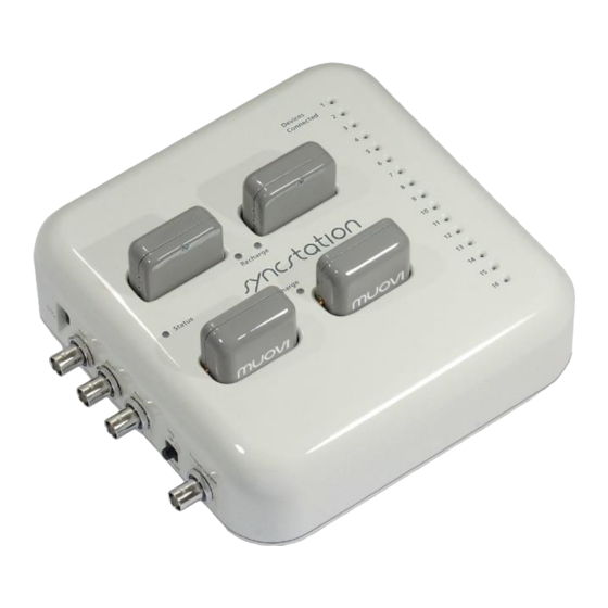
SyncStation - Controls, indicators and connectors The MuoviPro system is equipped with a recharging and synchronisation base called SyncStation, shown in Figure 7.2, which is capable of recharging up to 4 Muovi probes simultaneously. Next to the housing dedicated to each Muovi probe, on the SyncStation, there is a LED (see Fig. 7.2) that indicates the charging status of the respective probe. - Page 19 MuoviPro User Manual v.5.1 – December 2023 • Trigger signal generation, by pressing the related button (see Fig. 7.2) • Trigger output through BNC-OUT (see Fig. 7.2) The controls, indicators, and connectors on the SyncStation base are shown in Figure 7.2 and are described below.
-
Page 20: Connectors
MuoviPro User Manual v.5.1 – December 2023 7.2.1 Connectors On the SyncStation there are (with reference to Fig. 7.2): 6 connectors located on the left side, 1 connector located on the right side and 4 connectors located on the upper side: Power input: the SyncStation must be powered using the supplied DC power supply (12V ). -
Page 21: Led Indicators
MuoviPro User Manual v.5.1 – December 2023 Ethernet: The Ethernet port of the SyncStation can be connected directly to the PC or to a switch/router via an Ethernet cable. This port is used for data transfer from the SyncStation to the Charging connector: on the top panel of the base there are 4 slots for charging the Muovi probes, which are inserted into the slots using the input/charging connector. -
Page 22: Controls
MuoviPro User Manual v.5.1 – December 2023 The 16 "Connection LEDs" indicate the WiFi connection of the associated wireless devices. The SyncStation is designed to be able to receive signals from the four Muovi probes and from additional devices such as the Muovi+, Due+, Sessantaquattro, Sessantaquattro+ and Quattro+ probes. When one of these LEDs lights up, it means that the corresponding device is connected to the SyncStation and is ready to transmit data. -
Page 23: Use Of Muovipro
Muovi probe without the possibility of synchronisation with other probes or other devices. If a Muovi probe is used inside the MuoviPro system, there is no need to interfere with the WiFi interface, as it is managed in a totally automatic way by the SyncStation. As soon as the probe is turned on, it connects to the SyncStation and it is available to start data acquisition. -
Page 24: Signals
MuoviPro User Manual v.5.1 – December 2023 number of the Muovi probe and ID is the identification number of the Muovi probe that can range from 1 to 4. In this mode the Muovi probe acts as a DHCP server providing settings to devices connected to its network, but only one device at a time can connect to the network generated by the Muovi probe. - Page 25 MuoviPro User Manual v.5.1 – December 2023 The filter is implemented by subtracting the exponential moving average from the signals, obtained from: Mean_ChX[t] = (1-α) Mean_ChX[t-1] + α ChX[t] Where α is equal to 1/2 . The result is a high-pass filter with a cutoff frequency of 10.5 Hz, when sampling signals at 2000 Hz.
- Page 26 MuoviPro User Manual v.5.1 – December 2023 Resolution Input Range RMS R.T.I. Noise P-P R.T.I. Noise 16 bits 18,75 mV 286.1 nV 0.6 – 1.2 µV 3.6 – 7.8 µV 24 bits 3,3 V 286.1 nV 0.6 – 1.2 µV 3.6 –...
- Page 27 MuoviPro User Manual v.5.1 – December 2023 FIG. 8.1: IMU sensor placement and axis orientation. The two accessory channels contain information related to the RF synchronisation signal sent by the SyncStation, the use of the internal memory buffer of the Muovi probe, and a sample counter. In...
-
Page 28: Acquisition Electrodes And Patient Connection
MuoviPro User Manual v.5.1 – December 2023 the SyncStation. Time for processing the TR_CODE may vary, and the code can appear in a subsequence sample with respect to the sample where the trig pulse is detected. bit 7 Not used, fixed at 0. - Page 29 MuoviPro User Manual v.5.1 – December 2023 On the back of the connector of each matrix there is a rigid tab, which is used to facilitate the insertion and the removal of the matrix from the probe (see Fig. 8.2). The acquisition matrices are defined as semi-reusable because, for their use on a patient, they must be applied by interposing a layer of double- sided die cut foam and conductive cream between the matrix and the skin.
-
Page 30: Recharge Of The Muovi Probes
Power the SyncStation by plugging in the 12V power supply provided in the MuoviPro system KIT When a charging slot on the SyncStation is free, the associated charging LED is off Insert the Muovi probe to be recharged into a free slot. The associated charging LED lights up,... -
Page 31: Wireless Data Transfer
MuoviPro User Manual v.5.1 – December 2023 8.1.5 Wireless data transfer If one or more Muovi probes are used with the SyncStation, it acts as a hub and receives signals from all devices connected to it, adds data acquired from auxiliary channels, combines all information and forwards it to a PC connected via Ethernet. - Page 32 MuoviPro User Manual v.5.1 – December 2023 address and subnet mask must be in the same range as those of the Muovi probe or SyncStation. The internal web page can be opened by typing the IP address of the Muovi probe in the address bar of any browser.
- Page 33 MuoviPro User Manual v.5.1 – December 2023 IP address Device Serial number Notes 192.168.14.1 MVXXX-1 192.168.14.2 MVXXX-2 The Muovi probes have a fixed IP address obtained on the basis of Muovi serial number and ID. 192.168.14.3 MVXXX-3 192.168.14.4 MVXXX-4 One or both Muovi+ probes can be replaced by the 192.168.14.5...
- Page 34 MuoviPro User Manual v.5.1 – December 2023 FIG. 8.3: Muovi internal web page. General Information This section provides information that cannot be changed: serial number, MAC address, firmware version and battery level. To update the battery indicator you need to refresh the web page.
-
Page 35: Probe Nomenclature
8.1.7 Probe Nomenclature In order to help identify the Muovi probes, understand their role within the MuoviPro system, and allow you to reach the internal web page, each probe's serial number consists of a three-part code: MV123-4 Where: - “MV”: are the letters that identify the type of device (MV = Muovi, MP = Muovi+, DP = Due+, QP =... -
Page 36: Use Of The Syncstation
MuoviPro User Manual v.5.1 – December 2023 - “4”: a number that represents the probe ID and corresponds to the last part of the probe IP address. The IP address of all wireless devices is 192.168.14.X where X is the probe ID. So, for the example mentioned, the IP address is: 192.168.14.4. -
Page 37: Data Transfer To Pc
MuoviPro User Manual v.5.1 – December 2023 Network to wireless device Network to the PC Hidden WiFi dedicated exclusively to the connection of Description wireless devices Muovi, Muovi+, Due+, Ethernet to the PC for acquisition data Sessantaquattro, Sessantaquattro+ and Quattro+ IP SyncStation 192.168.14.100... - Page 38 MuoviPro User Manual v.5.1 – December 2023 For each connected and configured device, and for the auxiliary inputs, the SyncStation allocates a certain amount of memory as input buffer, such that 32 WiFi packets per probe are stored. The received data is temporarily written to the respective input buffers waiting to be processed and copied to an output buffer.
- Page 39 MuoviPro User Manual v.5.1 – December 2023 FIG. 8.4: Simplified graphical representation of data handling by the SyncStation: packets received via WiFi from the various active probes is accumulated in FIFO buffers as well as samples acquired from the auxiliary channels. When a minimum number of samples from all active devices are available, an output packet for the PC containing samples from all devices is sent via Ethernet to the PC.
- Page 40 MuoviPro User Manual v.5.1 – December 2023 If some probes are configured to acquire EMG signals and others to acquire EEG signals, the SyncStation performs 3 replications of the EEG samples to obtain all the data sampled with the highest sampling frequency, that is 2000 Hz.
- Page 41 MuoviPro User Manual v.5.1 – December 2023 Muovi+/ Sessantaquattro/ Sessantaquattro+ Mode Parameters Value Muovi+ probe channels 64 bioelectrical + 4 IMU + 2 Accessories Sessantaquattro+ channels 64 bioelectrical + 4 IMU + 2 Accessories Sessantaquattro channels 64 bioelectrical + 2 AUX + 2 Unused + 2 Accessories...
- Page 42 MuoviPro User Manual v.5.1 – December 2023 Quattro+ Mode Parameters Value Quattro+ probe channels 4 bioelectrical + 4 IMU + 2 Accessories Sampling frequency 2000 Hz Resolution 16 bit Sample dimension 16 byte Sample number in each WiFi packet WiFi packet dimension...
- Page 43 MuoviPro User Manual v.5.1 – December 2023 The two accessory channels contain information relating to the RF synchronisation signal generated by the SyncStation (present on the "SYNC" BNC), the use of the memory buffer inside the Muovi probe and a sample counter. In particular, the first accessory channel has a dedicated bit to indicate the status of...
-
Page 44: Syncstation Internal Web Page
MuoviPro User Manual v.5.1 – December 2023 The second accessory channel is a sample counter. This is incremented with each new sample acquired from the accessory inputs and can be used to check if one or more samples have been lost. The... - Page 45 MuoviPro User Manual v.5.1 – December 2023 FIG. 8.5: SyncStation internal web page General Information This section provides information that cannot be changed: serial number, MAC address, firmware version and the possibility to update the firmware. SyncStation firmware update is possible by uploading a file containing the firmware itself.
- Page 46 MuoviPro User Manual v.5.1 – December 2023 WiFi channel This section may be useful if you are unable to obtain a stable communication between your PC and SyncStation. In fact, if the Wifi channel to which the SyncStation is connected is saturated, unstable communication could occur.
-
Page 47: Troubleshooting
MuoviPro User Manual v.5.1 – December 2023 TROUBLESHOOTING This section describes the most common problems that may be found by MuoviPro users, with some suggestions to solve them. For problems not described in this section contact the technical support team of OT Bioelettronica. -
Page 48: Muovipro Maintenance And Storage
700 hPa to 1060 hPa It is recommended to turn off the MuoviPro system at the end of each measurement session, and to remove all connections. The MuoviPro system should be stored with all the enclosed accessories on a Warnings. - Page 49 Dispose of the device and accessories according to local regulations. Follow the regulations regarding the disposal of your country to ensure the correct disposal of MuoviPro and its accessories. For more information on disposal of this device, contact the Environment Department and local authorities.
-
Page 50: Risk Analysis
Compatibility MuoviPro is designed to be used in an electromagnetic environment with the characteristics specified below. The purchaser or user of MuoviPro is obliged to ensure that the device is used in an environment that complies with these specifications. Manufacturer’s declaration and guidelines – electromagnetic emissions... - Page 51 MuoviPro User Manual v.5.1 – December 2023 Manufacturer’s declaration and guidelines – electromagnetic immunity – casing door EMC reference Immunity test levels - Phenomenon standard or test Professional healthcare environment method EN 60601-1-2, EN 60601-2-40 and ETSI EN 301 489-1...
-
Page 52: Intended Use
MuoviPro User Manual v.5.1 – December 2023 INTENDED USE MuoviPro is a medical device intended for the study of the biomechanics of movement and the acquisition of bioelectrical signals from the neuromuscular system. The clinical applications of the system are in the context of:... -
Page 53: Technical Characteristics
MuoviPro User Manual v.5.1 – December 2023 TECHNICAL CHARACTERISTICS Model: MuoviPro Risk Class: I in compliance with the Regulation MDR 2017/745. Insulation Class: BF type with applied parts, in compliance with the European standard EN 60601-1 Basic UDI: 805697785PORTABLEEMG002SF Classification: IP20, based on liquids’... -
Page 54: Warranty
MuoviPro User Manual v.5.1 – December 2023 WARRANTY MuoviPro electronic parts are covered by a 24-month warranty starting from the purchasing date. Connection cables are covered by a 24-month warranty. The warranty is void in case of device violation or in case of intervention from unauthorised staff. - Page 56 Designed and produced by: OT Bioelettronica s.r.l. Via San Marino 21 10134 – Torino (TO) - ITALY Tel: +39.011.19720518 Fax: +39.011.19720519 www.otbioelettronica.it mail@otbioelettronica.it...
Need help?
Do you have a question about the MuoviPro and is the answer not in the manual?
Questions and answers