
Subscribe to Our Youtube Channel
Related Manuals for EMS 53-5414

Summary of Contents for EMS 53-5414
- Page 1 5000 VHF & UHF REMOTE RECEIVERS INSTALLATION AND PROGRAMMING INSTRUCTIONS MODEL NUMBERS 53 -5414 & 53 –5428...
-
Page 2: Table Of Contents
............................. 6 7. SOFTWARE CONFIGURATION ................7 8. MAIN CONTROL PANEL ENGINEERS MENU STRUCTURE ......... 11 9. TESTING THE SYSTEM ..................12 10. CONTROLLER INFORMATION ................15 ©2015 EMS Security Group Ltd. All rights reserved. TSD244 Iss 3 25/06/15 AJM... -
Page 3: Introduction
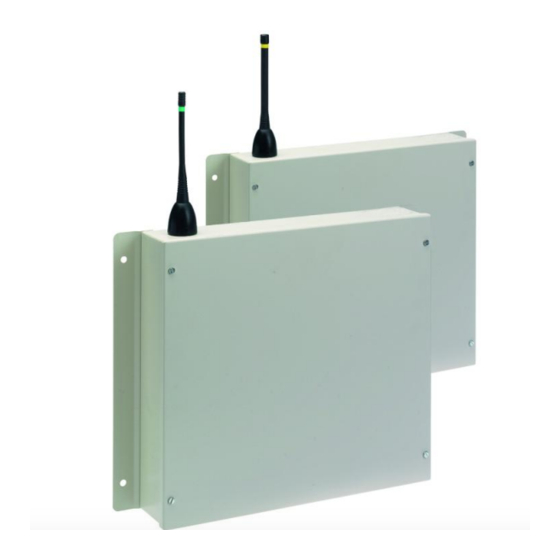
Control Panel. A block diagram of a system using the UHF remote receiver is shown in Figure 1. The Model 53-5414 is a VHF remote receiver capable of receiving VHF signals directly from all types of detectors, thus improving the overall range coverage of the system. -
Page 4: Tools & Test Equipment
5-5501/BP20/High gain aerial c/w 20 metres of low loss cable, wall mounting bracket and extension pole. 5-5501/BP30/High gain aerial c/w 30 metres of low loss cable, wall mounting bracket and extension pole. ©2015 EMS Security Group Ltd. All rights reserved. TSD244 Iss 3 25/06/15 AJM... -
Page 5: Vhf Remote Receiver Relevant High Gain Aerials
When all connections have been made to the remote receiver the battery can be connected, the lid can be re-fixed and mains voltage can then be applied. ©2015 EMS Security Group Ltd. All rights reserved. TSD244 Iss 3 25/06/15 AJM... -
Page 6: Vhf Remote Receiver
EMS 5000 FIREPOINT 6.2 VHF Remote Receiver The VHF remote receiver 53-5414 should be wired as shown in the supplied drawing P03077. The following paragraphs outline the installation in a step by step format. Remove the four lid retaining screws situated on the front cover. The front section of the unit can now be removed. -
Page 7: Software Configuration
Yes= Select Time | ** Eng. Config ** | Press the “YES” key and the screen will display: >Device Database < | Sounder Options Yes= Select Time ©2015 EMS Security Group Ltd. All rights reserved. TSD244 Iss 3 25/06/15 AJM... - Page 8 | Bus Remote Setup | Yes= Select Time | Device Table Press the “” key until the screen displays: >Re-start Bus < | Re-Online Device | YES = Select TIME ©2015 EMS Security Group Ltd. All rights reserved. TSD244 Iss 3 25/06/15 AJM...
- Page 9 | Enable Receiver key to change its status. Once set to “Enabled” press the >Enable Collector < | Monitor Traffic “NO” key. The screen will display: Yes= Select Time ©2015 EMS Security Group Ltd. All rights reserved. TSD244 Iss 3 25/06/15 AJM...
- Page 10 Now turn the control keyswitch to the “OFF” position and the screen will display: The Remote Receiver is now Status Normal programmed to the System. Date Time ©2015 EMS Security Group Ltd. All rights reserved. TSD244 Iss 3 25/06/15 AJM...
-
Page 11: Main Control Panel Engineers Menu Structure
View Network NUA YES = Finish TIME Network Name Control Routing Send Test Enabled Push YES to change Push NO to escape Push YES/NO TIME Figure 3 ©2015 EMS Security Group Ltd. All rights reserved. TSD244 Iss 3 25/06/15 AJM... -
Page 12: Testing The System
Once UHF Remote units have been installed and are communicating with the Control Panel, the transponder units which will send device information to the remote receiver should be installed (see transponder installation instructions for details). ©2015 EMS Security Group Ltd. All rights reserved. TSD244 Iss 3 25/06/15 AJM... - Page 13 EMS 5000 FIREPOINT ©2015 EMS Security Group Ltd. All rights reserved. TSD244 Iss 3 25/06/15 AJM...
- Page 14 EMS 5000 FIREPOINT ©2015 EMS Security Group Ltd. All rights reserved. TSD244 Iss 3 25/06/15 AJM...
-
Page 15: Controller Information
Battery space: 1 x 12volt 7Ah batteries (supplied) EMS only recommend: Yucel Model No: NP7- 12 or a battery of equivalent specification Recommended battery 5 years replacement intervals: ©2015 EMS Security Group Ltd. All rights reserved. TSD244 Iss 3 25/06/15 AJM... - Page 16 EMS 5000 FIREPOINT ©2015 EMS Security Group Ltd. All rights reserved. TSD244 Iss 3 25/06/15 AJM...
Need help?
Do you have a question about the 53-5414 and is the answer not in the manual?
Questions and answers