Zoom F6 Operation Manual
Multitrack field recorder
Hide thumbs
Also See for F6:
- Operation manual (28 pages) ,
- Quick manual (17 pages) ,
- Supplementary manual (16 pages)
Table of Contents
Advertisement
Operation Manual
You must read the Usage and Safety Precautions before use.
© 2019 ZOOM CORPORATION
Copying or reprinting this manual in part or in whole without permission is prohibited.
Product names, registered trademarks and company names in this document are the property of their respective companies. All trademarks and regis-
tered trademarks in this document are for identification purposes only and are not intended to infringe on the copyrights of their respective owners.
Proper display is not possible on grayscale devices.
Advertisement
Chapters
Table of Contents

Related Manuals for Zoom F6


Summary of Contents for Zoom F6
- Page 1 Operation Manual You must read the Usage and Safety Precautions before use. © 2019 ZOOM CORPORATION Copying or reprinting this manual in part or in whole without permission is prohibited. Product names, registered trademarks and company names in this document are the property of their respective companies. All trademarks and regis- tered trademarks in this document are for identification purposes only and are not intended to infringe on the copyrights of their respective owners.
-
Page 2: Notes About This Operation Manual
◎ The SD, SDHC and SDXC logos are trademarks. ◎ The Bluetooth® word mark and logo are registered trademarks of Blue- tooth® SIG, Inc. and these marks are used under license by Zoom Cor- poration. ◎ Other product names, registered trademarks and company names in this document are the property of their respective companies. -
Page 3: Introduction
LED level meters and various transport buttons can be used for in- This enables simultaneous backup recording and Internet live streaming. tuitive sound control. Combined with the F6 Control iOS app, iPhones and ● 360º audio iPads can also be used as large meters with excellent visibility. -
Page 4: Table Of Contents
Contents Notes about this Operation Manual Playback ................. 02 ......................... 51 Introduction Playing recordings ........................51 ........................03 Contents Mixing takes ..........................52 ......................... 04 Names of parts Monitoring the playback signals of specific tracks during playback ......54 ......................06 Connecting mics/other devices to Inputs 1–6 Changing the repeat playback setting ................ - Page 5 Timecode Appendix ........................122 ........................183 Timecode overview ......................122 Troubleshooting ........................183 Setting timecode ........................124 Metadata list .........................185 Setting the automatic timecode recording delay ............133 List of shortcuts ........................189 Setting timecode initialization used at startup ...............134 Block diagrams ........................190 Using USB functions Specifications........................197 ....................136 Exchanging data with a computer ..................136 Using as an audio interface ....................138...
-
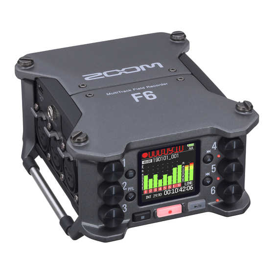
Page 6: Names Of Parts
Names of parts ■ Front Track knob Display Status indicator Red: Input enabled Green: Playback track enabled Orange: PFL monitoring FF/↑ button Unlit: Input disabled Home Screen: Select playback take Menu Screen: Select menu item MENU button Home Screen: Open Menu Screen Menu Screen: Return to previous RWD/↓... - Page 7 ■ Left side ■ Right side TIMECODE IN/OUT jack USB port LINE OUT jack Zoom wireless adapter (e.g. BTA-1) HEADPHONE jack POWER switch Headphone volume Inputs 4–6 Inputs 1–3 Inputs 1–6 TIMECODE IN/OUT TIP: Input to F6 (output from external device) 1:GND...
-
Page 8: Connecting Mics/Other Devices To Inputs 1-6
Connecting mics/other devices to Inputs 1–6 can record 6 individual tracks that correspond to Inputs 1–6 and a stereo mix of these inputs with left and right tracks. Mics and the outputs of instruments and audiovisual equipment, for example, can be connected to Inputs 1–6 and recorded to tracks 1–6. Connecting mics Connect dynamic and condenser mics with XLR plugs to Inputs 1–6. -
Page 9: Equipment Connection Examples
Equipment connection examples Recording is possible in a variety of situations like these. While filming Concert recording • Input 1: gun mic for main subject sound • Inputs 1–2: line inputs for outputs from mixer • Inputs 2–4: lapel mics for performers •... -
Page 10: Display Overview
Display overview ■ Home Screen Status icons Counter During recording: Elapsed/remaining recording time During playback: Elapsed/remaining playback time Stopped Paused Playing back Recording Power type and remaining amount Recording/playback USB: Power supply connected to port sample rate EXT: L battery Clip indicator AA: AA batteries Recording/playback take name... - Page 11 ■ Character input screen Text box Press Press Keyboard Operation indicator Press Press Press Automatic input button NOTE • • The following characters can be used in project names. • • (space) ! # $ ' ( ) + , - 0 1 2 3 4 5 6 7 8 9 ; = @ A B C D E F G H I J K L M N O P Q R S T U V W X Y Z [ ] ^ _ ` a b c d e f g h i j k l m n o p q r s t u v w x y z { }...
- Page 12 ■ Editing operations Move cursor in Use “ ←” and “ →” to move and press text box Select characters Press (vertical) Select characters Press (horizontal) Move the cursor to the character to input, and Confirm characters press Move cursor before the character to delete in the Delete characters text box, and press Complete editing Move cursor to "OK"...
-
Page 13: Preparations
Preparations Supplying power Power can be supplied three ways using AA batteries, an L battery or USB. ■ Using AA batteries ■ Using an L battery Loosen the screw in the battery cover on the bottom. Slide the battery in the direction of the arrow while pressing it toward the recorder. - Page 14 ■ Using a USB Type-C cable Connect the cable of the dedicated ZOOM AD-17 AC adapter to the USB port. Plug the dedicated AC adapter into an outlet. NOTE • • A 5V mobile battery (commercially-available) can also be connected.
-
Page 15: Loading Sd Cards
Loading SD cards Open the SD card slot cover, and insert an SD card. To remove the card: push it further into the slot and then pull it out. NOTE Before using SD cards that have just been purchased or that have been for- matted on a computer, they must be formatted. -
Page 16: Turning The Power On And Off
The ZOOM logo appears and the power turns on. NOTE Keep pressing it until the ZOOM logo appears on the LCD. NOTE • • The first time the power is turned on after purchase, the date/time must be set ( → P. 18). This setting can also be changed later. -
Page 17: Setting The Language
Setting the language menu display language can be changed. Press to select the desired language, and press to select SYSTEM, and press NOTE The first time the power is turned on after purchase, the language must be set. to select Language, and press... -
Page 18: Setting The Date And Time
Setting the date and time The date and time set on the are used when recording files, for example. The date format (order of year, month and day) can also be set. Press to select Date/Time, and press to select SYSTEM, and press ▶... - Page 19 ■ Setting the date and time When done setting, use to select Set to select Date/Time, and press Enter, and press This completes setting the date and time. ■ Setting the date format to select Set the date and time Date Format, and press Move cursor or change value: Change item value:...
-
Page 20: Setting The Power Supply Used
Setting the power supply used When using AA batteries, set the battery type so that the amount of remaining power can be shown accurately. The voltage of each power supply and the remaining battery charge can be checked on this menu page. Press to select Power Source, and press... - Page 21 ■ Setting the installed AA battery type to select Type, and press to select the type, and press NOTE • • When multiple power supplies are connected, they will be used in the fol- lowing order of priority. 1. USB (Power supply connected to USB port) 2.
-
Page 22: Recording
Recording Recording process Recording with the follows the process shown below. The data created for each recording occurrence is called a "take". Checking take Turning the Playing and Preparing to Recording information power on checking Connecting ( → P. 26) ( → P. 64) ( → P. 16) record ( → P. 51) -
Page 23: Setting The Recording File Format
Setting the recording file format Tracks Press Setting Explanation recorded A single poly file will be created that contains Poly audio for multiple tracks. to select Selected A single mono file is created for each mono tracks 1-6 REC, and press Mono/Stereo track and a single stereo file is created for each stereo track. -
Page 24: Selecting Inputs And Adjusting Levels
Selecting inputs and adjusting levels Select which among Inputs 1–6 to use. Inputs will be recorded on tracks with the same numbers. For example, Input 1 will be recorded on track 1 and Input 2 will be recorded on track 2. Selecting inputs NOTE •... - Page 25 ■ Adjusting input levels to select Press Trim, and press to select INPUT, and press to adjust the input level, and press to select PFL, and press HINT • • This can be set in a range from +12 to +75 dB when the input source is set to Mic, from –8 to +55 dB when set to Line, and from –35 to +30 dB when set to USB.
-
Page 26: Recording
Recording Press to pause. NOTE • • Pausing occurs at whole second increments. • • When recording is paused, a mark is added at that point. Press to resume recording. • • A maximum of 99 marks can be added to a take. HINT •... -
Page 27: Setting The Sampling Rate
Setting the sampling rate The sampling rate used to record files can be set. Press to select the sampling rate, and press to select REC, and press Setting Explanation 44.1 kHz, 48 kHz, 88.2 These are standard sampling rates. kHz, 96 kHz, 192 kHz to select Select this when recording video at 23.976 frames Sample Rate, and press... - Page 28 NOTE • • 192 kHz cannot be selected when the recording mode is Float (32bit) and the LR track is on. • • When 192 kHz is selected, Dual (16+32bit) and Dual (24+32bit) cannot be set. • • When the recording mode is MP3, only 44.1 kHz and 48 kHz can be selected.
-
Page 29: Setting The Recording Mode (Bit Depth)
Setting the recording mode (bit depth) Set the recording mode. The bit depth of WAV files recorded by the will change according to the mode setting. Press to select the mode, and press to select REC, and press HINT The setting options are Linear (16bit), Linear (24bit), Float (32bit), Dual (16+32bit), Dual (24+32bit) and MP3. - Page 30 Mode setting Mode name Explanation These modes record ordinary 16/24- Linear (16bit) bit WAV files. Adjust input (trim) levels so that Linear the clip indicators do not light when Linear (24bit) recording. The level meters show input levels after adjustments. This mode records 32-bit float WAV files.
-
Page 31: Setting Mp3 File Bit Rate (Mp3)
Setting MP3 file bit rate (MP3) The bit rate used for recording MP3 files can be set. Press to select MP3, and press to select REC, and press Press to return to the REC screen. to select Mode, and press Confirm that the Mode is set to MP3. - Page 32 to select the bit rate, and press HINT This can be set to 128 kbps, 192 kbps or 320 kbps.
-
Page 33: Setting The Lr Track
Setting the LR Track ■ Enabling the LR track to select Press On/Off, and press to select REC, and press to select On, and press to select LR Track, and press • • NOTE • • Off: This disables the LR Track. •... - Page 34 ■ Adjusting the L/R track volume to select Press LR Fader, and press to select REC, and press to change the LR fader value, adjust- ing the LR track volume. to select LR Track, and press NOTE Pressing when the Home Screen is open will also open the LR/ Line Out setting screen.
-
Page 35: Capturing Audio Before Recording Starts
Capturing audio before recording starts The input signal is always buffered for a set amount of time, so it can be captured for up to 6 seconds before is pushed (pre-recording). This is useful when is pressed late, for example. Press to select On, and press... -
Page 36: Setting The Recording Time Display
Setting the recording time display During recording, either the elapsed recording time or the remaining possible recording time can be shown. Press to select Display, and press to select SYSTEM, and press to select Time Display, and press to select Settings, and press... - Page 37 to select NOTE When recording for a long time, if the file size Recording, and press exceeds 2 GB, recording will continue in a new file and the recording time will reset. This can be changed, however, so that it is not reset and the total recording time is shown.
-
Page 38: Setting The Playback Time Display
Setting the playback time display During playback, either the elapsed playback time or the remaining playback time can be shown. Press to select Display, and press to select SYSTEM, and press to select Time Display, and press to select Settings, and press to select Playing, and press... - Page 39 to select the time to show, and press...
-
Page 40: Folder And File Structure
Folder and file structure When recording with the , folders and files are created on the SD card in the following manner. folders and files are used to manage scenes and takes as a rule. Folder and file structure NOTE •... - Page 41 ■ Take names ■ Audio file names File names given by the differ according to polyphonic, mono and Structure Explanation Scene name: Select none, the folder stereo file formats. Track numbers and other data are added to file Scene001-001 name, the date or a name input by the names.
-
Page 42: Move The Previously Recorded Take To The False Take Folder
Move the previously recorded take to the FALSE TAKE folder. If the just recorded take was a failure, a shortcut can be used to move the recording to the FALSE TAKE folder. Open the Home Screen. While pressing , press HINT •... -
Page 43: Recorded Take Settings
Recorded take settings Changing the note for the next take recorded Characters can be input, for example, as a note to use as metadata in files. ■ Editing notes Press to select to select Note, and press REC, and press to select to select Edit, and press... - Page 44 ■ Selecting notes from the history list Edit the note. to select See "Character input screen" ( → P. 11) for how to input History, and press characters. NOTE to select This note is written to the <NOTE> metadata. the desired history item, and press NOTE The history list will be erased if the Factory Reset function is used.
-
Page 45: Setting And Managing Recorded Scene Names
Setting and managing recorded scene names The way scenes are named (name mode) can be set. Setting how scenes are named (mode) Press to select to select Scene Name, and press REC, and press to select to select Mode, and press Metadata, and press ▶... - Page 46 ■ Changing scene names Setting Explanation The name of the currently selected folder is used as the scene If Scene Name Mode is set to User Name, set the scene name used like name. this. can be used to advance the scene number by 1. After Current advancing the scene number by 1, the corresponding folder will to select...
- Page 47 NOTE to select • • The scene name is written to the <SCENE> metadata. the desired history • • Spaces and @ marks cannot be input at name beginnings. item, and press ■ Selecting a scene name from the history list to select User Name, and press NOTE...
-
Page 48: Changing The Track Name Of The Next Take Recorded (Track Name)
Changing the track name of the next take recorded (Track Name) The track name set with the following procedure will be given to the next recorded track. Press to select Track Name, and press to select REC, and press to select a track, and press to select Metadata, and press... - Page 49 ■ Editing the track name. ■ Selecting a track name from the history list to select to select Edit, and press History, and press Edit the track name. to select See "Character input screen" the desired history ( → P. 11) for how to input item, and press characters.
-
Page 50: Changing The Number Of The Next Take Recorded
Changing the number of the next take recorded The number given to the next recorded take can be changed when the Home Screen is open. While pressing , press to increase or decrease the take num- ber, and press NOTE This function cannot be used during recording and playback or when the Scene Name Mode is set to Date. -
Page 51: Playback
Playback Playing recordings HINT • • The longer is pressed and held, the faster the speed of searching backward/forward. • • An "Invalid Take!" message will appear if the selected take is not valid. • • A "No Take!" message will appear if no playable take exists. •... -
Page 52: Mixing Takes
Mixing takes The volume and panning of each track during playback can be changed. ■ Setting faders ■ Setting the panning Touch on the Home Press Screen ( → P. 10). to select INPUT, and press Turn to adjust the input signal level. to select PFL, and press NOTE... - Page 53 Parameter Setting range Explanation to select the Fader desired track, and press Mute, −48.0 – +24.0 dB (in Float mode) Adjusts the input signal level. Fader Mute, −60.0 – +60.0 dB (in Linear mode) Adjusts the stereo balance of L100 – Center – R100 the sound.
-
Page 54: Monitoring The Playback Signals Of Specific Tracks During Playback
Monitoring the playback signals of specific tracks during playback The playback signals of specific tracks can be monitored using SOLO mode. Open the Home Screen. to select INPUT, and press NOTE Press to start playback. SOLO mode can only be used with tracks that can be played back (indica- tors lit green). - Page 55 to select the track to monitor, and press...
-
Page 56: Changing The Repeat Playback Setting
Changing the repeat playback setting The repeat setting used during playback can be changed. Press to select the repeat mode, and press to select PLAY, and press Setting Explanation Play One Only the selected take will be played. (single playback) Play All Takes will be played back continuously from the to select... -
Page 57: Take And Folder Operations
Take and folder operations Working with takes and folders The Finder allows the viewing of the contents of SD cards, takes and folders and the creation of project/scene folders. It also allows the setting and deletion of recording/playback folders along with viewing their information, for example. ■... -
Page 58: Creating Folders
■ Creating folders ■ Selecting the take recording/playback folder Folders can be created inside the currently selected SD card/folder. Use this procedure to select the folder that contains the take to be played back or the folder to use for recording takes and return to the to select Home Screen. -
Page 59: Checking Take Marks And Using Them For Playback
■ Checking take marks and using them for playback ■ Changing folder and take names A list of the marks in a recorded take can be shown. Press and hold to open the Option screen. Press and hold to open the Option screen. to select to select Rename, and press... -
Page 60: Deleting Folders And Takes
■ Deleting folders and takes to select Press and hold to open the Option screen. Execute, and press to select Delete, and press NOTE • • Deleted folders and takes are not immediately erased from the SD card. They are moved to the TRASH folder. •... - Page 61 ■ Take selected ■ Checking folder and take information TC: Timecode Press and hold to open the Option screen. FPS: Timecode frame rate Len: Take recording length to select Fmt: Take sample format Info, and press Date: Date Time: Time Size: Take size ■...
-
Page 62: Emptying The Trash/False Take Folders
■ Emptying the TRASH/FALSE TAKE folders to select to select Empty, and press TRASH or FALSE TAKE. TRASH folder to select Execute, and press FALSE TAKE folder NOTE • • Emptying the TRASH folder will completely erase the data in it. •... -
Page 63: Overview Of Metadata (Take Information) Stored In Files
Overview of metadata (take information) stored in files ■ WAV file metadata writes a variety of information (metadata) to files during record- ing. The metadata saved in files recorded by the in WAV format is col- When these files are read by an application that supports metadata, the lected in BEXT (Broadcast Audio Extension) and iXML chunks. -
Page 64: Checking And Editing Take Metadata
Checking and editing take metadata Press to select a folder, and press to select FINDER, and press to select a take, and press to select an This opens the Option screen. SD card, and press See "Take and folder operations" for how to use the Finder ( → P. 57). - Page 65 ▶ Continue to one of the following procedures. Edit the note. Checking and editing notes ………………………………………………… P. 65 See "Character input screen" Selecting notes from the history list …………………………………… P. 66 ( → P. 11) for how to input Checking and editing scene names …………………………………… P. 66 characters.
-
Page 66: Selecting Notes From The History List
■ Selecting notes from the history list ■ Checking and editing scene names to select to select Note, and press Scene/Take, and press to select to select History, and press Scene, and press to select to select the desired history Edit, and press item, and press NOTE... -
Page 67: Selecting A Scene Name From The History List
Edit the scene name. to select See "Character input screen" History, and press ( → P. 11) for how to input characters. to select NOTE the History item to use, The scene name is written to the <SCENE> metadata. ■ Selecting a scene name from the history list and press to select Scene/Take, and press... -
Page 68: Checking And Editing Take Names
■ Checking and editing take numbers ■ Editing operations Move cursor or change value: Press to select Select parameter to change: Press Scene/Take, and press HINT This can be set from 1 to 999. NOTE The take number is written to the <TAKE> metadata. to select When done changing, Take, and press... -
Page 69: Circling Takes
■ Circling takes ■ Changing tape names An @ mark can be added to the beginning of the name of the best take to select to make it stand out. This is called a "circled take". Tape Name, and press to select Circle, and press Edit the folder (tape) name. -
Page 70: Changing Project Names
■ Changing project names ■ Checking and editing the track names to select Proj- to select Track Name , and press ect Name, and press Edit the project name. to select See "Character input screen" a track, and press ( → P. 11) for how to input characters. -
Page 71: Selecting A Track Name From The History List
■ Selecting a track name from the history list Edit the track name. to select See "Character input screen" ( → P. 11) for how to input Track Name, and press characters. NOTE to select The track name is written to the <TRACK> <NAME> metadata. a track, and press to select History, and press... - Page 72 to select the desired history, and press NOTE The history list will be erased if the Factory Reset function is used.
-
Page 73: Writing A Sound Report
Writing a sound report A sound report includes information about recording times and takes. Reports can be written as CSV format files (F6_[folder name].CSV). Comments written in sound reports can also be edited. Press to select Sound Report, and press to select FINDER, and press ▶... - Page 74 ■ Writing sound reports ■ Editing comments to select to select Create, and press Info, and press to select to select Execute, and press Edit, and press This writes the sound report inside the selected SD card or folder. NOTE Edit the comment.
- Page 75 ■ Selecting comments from the history list to select to select the desired history Info, and press item, and press NOTE The history list will be erased if the Factory Reset function is used. to select History, and press...
-
Page 76: Input Settings
Input settings Adjusting the input signal monitoring balance The volume of each track can be adjusted when monitoring input signals. Open the Home Screen HINT ( → P. 10). The fader setting range is muted and –48.0 to +24.0 dB. NOTE • • Mix settings are saved separately for each recorded take and can be changed during playback ( → P. 52). -
Page 77: Monitoring The Input Signals Of Specified Tracks
Monitoring the input signals of specified tracks The input signals of specified tracks can be monitored. Even tracks that have not been set to record can be input to the PFL screen and their input sounds monitored. This is convenient when using tracks as return inputs. Carious settings can be made for selected tracks. -
Page 78: Setting The Input Source
Setting the input source The input source and phantom power on/off status can be set for each track. Press to select a track, and press to select INPUT, and press to select Source, and press to select PFL, and press to select the input source, and press... - Page 79 Setting Explanation Use when connecting a mic or other equipment with a low input level. Mic (PH) Use for mic level with phantom power. Use when connecting line level equipment. Line The input level will be reduced 20 dB compared to when Mic is selected.
-
Page 80: Setting The Monitoring Volume On The Pfl Screen
Setting the monitoring volume on the PFL screen On the PFL screen, the monitoring sound can be set to be either pre-fader listening (PFL) or fader solo (SOLO). Press to select a track, and press to select INPUT, and press to select Monitor, and press to select... - Page 81 Setting Explanation On the PFL screen, monitor the pre-fader sound. SOLO On the PFL screen, monitor the post-fader sound. NOTE • • When the PFL screen is open during playback, the monitoring sound will be post-fader (SOLO) regardless of the setting. •...
-
Page 82: Cutting Low-Frequency Noise
Cutting low-frequency noise The high pass filter can cut low frequencies to reduce the sound of wind, vocal pops and other noise. Press to select a track, and press to select INPUT, and press to select HPF/Limiter, and press to select PFL, and press to select HPF, and press... - Page 83 to select the desired cutoff fre- quency, and press HINT This can be set to Off or between 10 and 240 Hz.
-
Page 84: Input Limiter
Input limiter The limiter can prevent distortion by reducing input signals that have Press excessively high levels. to select Input signal Level INPUT, and press Threshold Signal after limiter Attack Release Time to select time time When the limiter is ON, if the input signal level exceeds the set thresh- PFL, and press old value, the input signal level will be suppressed to prevent the sound from distorting. - Page 85 Using the limiter to select to select HPF/Limiter, and press On/Off , and press to select to select Limiter, and press the setting, and press ▶ Continue to one of the following procedures. Using the limiter ……………………………………………………………………… P. 85 Setting the type ……………………………………………………………………… P. 87 Setting the threshold ………………………………………………………………...
- Page 86 On (Normal) NOTE Sometimes peaks remain When set to On (Advanced), the input latency of the increases 1 ms. When monitoring sounds being recorded with a mic in real-time, increased Threshold latency can cause interference between the sound being recorded that is transmitted through the air and the delayed monitored sound, possibly making accurate monitoring difficult.
-
Page 87: Setting The Type
■ Setting the type ■ Setting the threshold This sets the base level from which the limiter operates. to select to select Type, and press Threshold, and press to select to adjust the type, and press the setting, and press Setting Explanation Only peaks that exceed the threshold are attenuated. -
Page 88: Setting The Attack Time
■ Setting the attack time ■ Setting the release time This sets the amount of time until compression starts after the input This sets the amount of time until compression stops after the input signal exceeds the threshold. signal goes below the threshold. to select to select Attack Time, and press... -
Page 89: Setting The Target Level
■ Setting the target level When the limiter On/Off setting is set to On (Advanced), use this to set the target output level for the signal. to select Tar- get Level, and press to adjust the setting, and press HINT •... -
Page 90: Inverting The Input Phase
Inverting the input phase The phase of the input signal can be inverted. This is useful when sounds cancel each other out due to mic settings. Press to select a track, and press to select INPUT, and press to select Phase/Delay, and press to select PFL, and press... - Page 91 to select Phase Invert, and press to select On, and press...
-
Page 92: Changing The Phantom Power Settings
Changing the phantom power settings can provide phantom power. The voltage can be set to +24V or +48 V and it can be turned on/off for each input separately. HINT Press Phantom power is a function that supplies power to devices that require an external power supply, including some condenser mics. - Page 93 ■ Setting the voltage ■ Disabling phantom power during playback to select to select Voltage, and press Power Saving, and press to select the to select voltage, and press On (PH off during play- back), and press Setting Explanation HINT Phantom power is supplied even during playback.
-
Page 94: Applying Delay To Input Signals
Applying delay to input signals If there are differences in the timing of input sounds, use this function to correct them when recording. Press to select a track, and press to select INPUT, and press to select Phase/Delay, and press to select PFL, and press to select... - Page 95 to adjust the delay time, and press HINT This can be set from 0 to 30.0 ms. NOTE When Sample Rate is set to 192 kHz, Delay is disabled.
-
Page 96: Linking Inputs As A Stereo Pair
Linking inputs as a stereo pair By enabling the stereo link for tracks 1/2, 3/4 or 5/6, the corresponding Inputs (1/2, 3/4 or 5/6) can be handled as a stereo pair. When linked, Input 1, 3 or 5 will be the left channel and Input 2, 4 or 6 will be the right channel. ■... - Page 97 Setting Explanation to select Stereo When stereo-linked, inputs are handled normally. When stereo-linked, signals from mid-side mics are converted to Input Link, and press ordinary stereo. NOTE • • When stereo-linked, odd tracks are handled as left and even tracks as right channels.
-
Page 98: Adjusting Multiple Track Input Levels Together
Adjusting multiple track input levels together The input levels of multiple tracks can be linked and adjusted at the same time. Press to select Trim Link, and press to select INPUT, and press to select a track to link, and press to select Link Settings, and press Clear all... -
Page 99: Changing The Automatic Mixing Setting
Changing the automatic mixing setting When using multiple mics to capture audio during a meeting, for example, automatically attenuating the inputs of mics that are not in active use pro- vides the following benefits. · The likelihood of feedback is reduced. ·... - Page 100 NOTE • • The following functions and settings cannot be used with this function. − The sampling rate cannot be set to 192 kHz. − The Ambisonic format cannot be set to any value other than Off. • • When monitoring sounds being recorded with a mic in real-time, increased latency can cause interference between the sound being recorded that is transmitted through the air and the delayed monitored sound, possibly making accurate monitoring difficult.
-
Page 101: Setting The Ambisonic Format
Setting the Ambisonic format By connecting mics that can output Ambisonic A-format signals to Inputs 1–4, audio can be converted to Ambisonic B-format and recorded. Press to select Input Link, and press to select INPUT, and press to move the cursor to Ambison- to select Link ics, and press Settings, and press... - Page 102 FuMa to select This converts the signals from Inputs 1–4 to the Ambisonic FuMa Settings, and press B-format, and saves them as a 4-channel polyphonic file. AmbiX This converts the signals from Inputs 1–4 to the Ambisonic AmbiX B-format, and saves them as a 4-channel polyphonic file. Format: FuMa, AmbiX to select Ambisonics...
- Page 103 Ambisonics A HINT • • Ambisonic can also be set during use as an audio interface (Multi Track). This saves the signals from Inputs 1–4 as a 4-channel polyphonic file • • Even when Ambisonic format is not Off, PFL buttons can be selected to without converting them to an Ambisonic B-format.
-
Page 104: Setting The Mic Position Used For Ambisonic Recording
Setting the mic position used for Ambisonic recording By setting the mic orientation used during Ambisonic recording as an parameter, proper positioning can be maintained when converting to Am- bisonic B format if the mic orientation is changed from upright, upside down or horizontal. Press to select Input Link, and press... - Page 105 Upright to select Mic Position, and press Front to select the mic orientation, and press Upside Down Setting Explanation Upright Use this setting to record with the mic upright. HINT Upside Down Use this setting to record with the mic upside down. •...
-
Page 106: Output Settings
Output settings Setting signals sent to the headphone output Signals sent to the headphone output can be set to either prefader or postfader for each track. Saving 10 setting combinations (Setting 1–Setting 10) it is possible. Press to select Routing, and press to select OUTPUT, and press to select... - Page 107 ▶ Continue to one of the following procedures. NOTE • • L/R and line outputs cannot be set to prefader. Setting the routing ……………………………………………………………… P. 107 • • When AIF with Rec is set to On, USB track 1–4 can be assigned. Using mono headphone output …………………………………………...
- Page 108 ■ Monitoring mid-side stereo signals Signals from a mid-side stereo mic can be converted to an ordinary ste- reo signal for monitoring. to select MS, and press Press NOTE • • This is disabled for tracks that have input linking set to MS. •...
-
Page 109: Outputting Alerts Through Headphones
Outputting alerts through headphones The volume can be adjusted for alerts output from headphones when, for example, recording starts and stops. Press to select Alert Vol, and press to select OUTPUT, and press to adjust the volume, and press to select Head- phone Out, and press HINT •... -
Page 110: Setting The Headphone Output Volume Curve
Setting the headphone output volume curve The volume curve used when adjusting the headphone volume knob can be set. Press to select Vol Curve, and press to select OUTPUT, and press to select a curve, and press to select Head- phone Out, and press Setting Explanation... -
Page 111: Boosting Headphone Output To Alleviate Interference From Recorded Sound
Boosting headphone output to alleviate interference from recorded sound Boosting the headphone output alleviates the interference of sound waves traveling through the air with the headphone monitoring signal, enabling more accurate monitoring of the sound being recorded. Press to select Dig- ital Boost, and press to select OUTPUT, and press... - Page 112 NOTE In situations where the sound being recorded can be heard at the head- phone monitoring position, sound waves traveling through the air can inter- fere with the sound heard from the headphones, altering the monitored sound. The more the sound heard through the headphones is delayed and the lower its volume, the greater the impact of the sound waves.
-
Page 113: Setting The Output Level
Setting the output level The Line Out output level can be changed. Press to select Level, and press to select OUTPUT, and press to select Line Out, and press to select Line Out, and press to adjust the output level, and press... - Page 114 HINT NOTE • • See the manual of the connected device for information about its This can be set to Mute or from −48.0 to +12.0 dB operation. • • If the automatic gain control function on the other device is on, turn it off. ■...
-
Page 115: Applying Delay To The Output
Applying delay to the output By delaying output, timing differences for audio input into another device can be corrected. Press to select Delay, and press to select OUTPUT, and press to adjust the delay in frames, and press to select Line Out, and press HINT This can be set from 0.0 to 10.0 frames. -
Page 116: Output Limiter
Output Limiter Using a limiter on the output can protect devices connected to the output jacks. HINT to select For details about the limiter, see “Input limiter” ( → P. 84). Limiter, and press Press to select OUTPUT, and press ▶ Continue to one of the following procedures. Using the limiter ……………………………………………………………………... -
Page 117: Using The Limiter
■ Using the limiter ■ Setting the type to select to select On/Off, and press Type, and press to select to select On, and press the type, and press Setting Explanation Only peaks that exceed the threshold are attenuated. There is Hard Knee no effect below the threshold. -
Page 118: Setting The Threshold
■ Setting the threshold ■ Setting the attack time This sets the base level from which the limiter operates. This sets the amount of time until compression starts after the input signal exceeds the threshold. to select to select Threshold, and press Attack Time, and press to adjust to adjust... -
Page 119: Setting The Release Time
■ Setting the release time ■ Linking the limiter This sets the amount of time until compression stops after the input The line output limiters can be linked or applied independently. signal goes below the threshold. to select to select Link, and press Release Time, and press to select... -
Page 120: Selecting Signals Sent To The Line Outputs
Selecting signals sent to the line outputs The type of signal sent to the line outputs can be set to either prefader or postfader for each track. Press to select Routing, and press to select OUTPUT, and press to select Tracks routed to left line output Line Out, and press... - Page 121 NOTE • • When AIF with Rec is set to On, USB track 1–4 can be assigned. • • Tracks 1–6 can be set to prefader or postfader. • • The L/R tracks can only be set to postfader. • • Tracks 1–6, L/R, and USB 1–4 cannot be set at the same time. Selecting one type will deselect the other.
-
Page 122: Timecode
Timecode Timecode overview can input and output SMPTE timecode. Timecode is time information written to data when recording video and audio. It is used for video editing, control of other devices, and synchroniza- tion of audio and video, for example. ■... - Page 123 ■ Connection example ■ Inputting timecode Connections like the following are possible according to application. Timecode is transmitted from the timecode generator. Both the and the video camera receive timecode and record it with Synchronizing with a video camera their audio and video data. The input timecode can also be used to synchronize the audio clock of records with a mic input and transmits timecode.
-
Page 124: Setting Timecode
Setting timecode Use to set the timecode mode, timecode output when record- Press Mode ing is stopped, synchronization with audio clock, and internal timecode operation when there is no external timecode input. to select Use to set the frame rate of the internal timecode. Use to set jamming of the timecode input through the TIME- TIMECODE, and press CODE IN/OUT jack by the internal timecode. -
Page 125: Setting The Mode
■ Setting the mode Setting Explanation No timecode will be written to the recording file. The following types of settings can be made. Timecode will not be output from the TIMECODE IN/OUT jack. • Whether the generates timecode or receives external timecode Internal timecode will be generated regardless of the recording •... - Page 126 ■ Outputting timecode only when recording NOTE • • Timecode will continue to be output when recording/playback is paused. Whether or not timecode is output from the TIMECODE IN/OUT jack • • This cannot be set when Mode is set to Off, Ext or Ext Auto Rec. when recording is stopped can be set.
-
Page 127: Synchronizing Audio Clock With External Timecode
■ Synchronizing audio clock with external timecode NOTE • • When there is no external timecode, the internal audio clock is enabled to to select preserve continuity. • • This cannot be set when Mode is set to Off, Int Free Run, Int Rec Run or Mode, and press Int RTC Run. -
Page 128: Setting The User Bits For Internal Timecode
■ Setting the user bits for internal timecode to select User bits are data that can be set for inclusion in the timecode. Up to 8 On, and press numbers (0–9) and letters (A–F) can be included. Recording date infor- mation, for example, can be useful when editing later. - Page 129 ■ Setting the user bits (Ubits) to select to select the mode, and press Ubits, and press Setting Explanation uu uu uu uu These values can be set as desired on the Edit screen. The month, day and year are entered automatically in that to select mm dd yy uu order using the RTC setting.
-
Page 130: Setting The Frame Rate For Internal Timecode
Setting Explanation When done setting, use This is the most common frame rate used with HD cameras 23.976ND and other high-definition video recording. The count is slower to select than the actual time by 0.1%. Enter, and press This is the standard frame rate used for recording film. This is 24ND also used with HD cameras. -
Page 131: Jamming Internal Timecode
■ Jamming internal timecode ■ Restarting internal timecode with a specified value Timecode input through the TIMECODE IN jack is used to set internal to select timecode Jam, and press to select Jam, and press to select Restart, and press to select Jam, and press Set the restart value. - Page 132 to select Restart, and press...
-
Page 133: Setting The Automatic Timecode Recording Delay
Setting the automatic timecode recording delay If set to record automatically when external timecode is received, unnecessary recording could occur if timecode is received for a brief amount time. In order to prevent this, the amount of time until recording starts after timecode is received can be set. Press to adjust the time, and press... -
Page 134: Setting Timecode Initialization Used At Startup
Setting timecode initialization used at startup When the is turned off, the internal timecode stops, so the timecode is automatically initialized (jammed) during startup. The value that is used for jamming at that time can be set. ■ Setting how timecode is initialized at startup Press to select to select... - Page 135 ■ Correcting timecode errors after the power has been Calibration completes. turned off When the Start TC Mode is set to RTC, timecode precision will decrease if the power is turned off. This function can be used to improve preci- sion to almost 0.2 ppm even if the power is turned off.
-
Page 136: Using Usb Functions
Using USB functions Exchanging data with a computer By connecting with a computer, data on the cards can be checked and copied. ■ Connecting to select SD Press Card Reader, and press to select SYSTEM, and press Use a USB cable to connect the and the computer. - Page 137 ■ Disconnecting Disconnect on the computer. Windows: Select with "Safely Remove Hardware”. macOS: Drag the icon to the Trash and drop it. NOTE Always conduct computer disconnection procedures before removing the USB cable. Disconnect the cable from the computer and the and press...
-
Page 138: Using As An Audio Interface
This is a 6-in/4-out connection mode for Mac/Windows and sends tracks 1–6 as separate signals (cannot be used with Multi Track iOS devices). (PC/Mac) A driver is necessary for use with Windows. Download the driver from the ZOOM website (www.zoom.co.jp/). - Page 139 ■ Disconnecting Use a USB cable to connect the with the computer Press or iOS device. to select Exit, and press to select Exit, and press Disconnect the cable from the computer or iOS device and the...
-
Page 140: Using Sd Card Recording And Audio Interface Functions At The Same Time
Using SD card recording and audio interface functions at the same time In addition to SD card recording, a computer can also be used to record a backup. ■ Connecting to select AIF Press with Rec, and press to select SYSTEM, and press to select On, and press... - Page 141 Off, and press • • A driver is necessary for use with Windows. Download the driver from the ZOOM website (www.zoom.co.jp/). • • When AIF with Rec is set to On, the sample rate cannot be changed. • • When AIF with Rec is set to On, files with sample rates that differ from setting cannot be played.
-
Page 142: Audio Interface Settings
Audio interface settings The following settings can be made when using the as an audio interface. ■ Setting loop back (Stereo Mix only) ■ Mixing inputs This function mixes the playback sound from the computer or iOS de- The mix balance of the inputs can be adjusted. Input signals will be vice with the input and sends the mix back to the computer or iOS sent to the computer or iOS device using the balance settings made... -
Page 143: Using An Frc-8 As A Controller
Using an FRC-8 as a controller When an is connected to the , it can be used to adjust settings, including trim, fader and pan. NOTE to select cannot be used when operating with AA batteries. When mul- FRC-8, and press tiple power supplies are connected to an , the power supply being used will automatically change according to the remaining battery charge. - Page 144 NOTE • • When disconnecting the , select Disconnect before unplugging the USB cable • • Select Connect and press to supply bus power from the USB port. When bus power is being supplied, do not connect any device other than .
-
Page 145: Setting The Type Of Keyboard Connected To The Frc-8
Setting the type of keyboard connected to the FRC-8 A PC keyboard can be connected to the and used to input characters. Set the type to use the PC keyboard connected to the Press to select FRC-8, and press to select SYSTEM, and press to select Key- board Type, and press... - Page 146 to select the type, and press Setting Explanation This setting is for English-language keyboards. This setting is for Japanese keyboards.
-
Page 147: Setting User Keys For The Frc-8
Setting user keys for the FRC-8 Functions can be assigned to the user keys. Press to select FRC-8, and press to select SYSTEM, and press to select User Key, and press to select USB, and press... - Page 148 to select the key to which to assign a function, and press to select the function to assign, and press Setting Explanation None No function is assigned. Add marks to WAV format takes during recording and Mark playback. Key Hold Use to disable the controls set with Key Hold Target.
-
Page 149: Setting The Frc-8 Led Brightness
Setting the FRC-8 LED brightness The brightness of the LEDs on the front of the can be adjusted. Press to select FRC-8, and press to select SYSTEM, and press to select LED Brightness, and press to select USB, and press... - Page 150 to adjust the brightness, and press HINT This can be set from 5 to 100.
-
Page 151: Updating The Frc-8 Firmware
Updating the FRC-8 firmware firmware version can be checked and updated to the latest version. The latest update file can be downloaded from the ZOOM website (www.zoom.co.jp). as a controller" ( → P. 143), and See "Using an to select connect the... - Page 152 ■ Checking the firmware versions ■ Updating the firmware to select to select Firmware , and press Firmware, and press to select to select Version, and press Update, and press to select Update, and press...
- Page 153 NOTE Do not turn the power off, remove an SD card or disconnect the USB cable during an update. Doing so could cause the to become unstartable. After the update completes, turn the power off.
-
Page 154: Operating With An Ios Device
SYSTEM, and press operation manual for the iOS device that you are using to remove the that is registered as a Bluetooth device. • • Then, after you launch F6 Control, the password input screen will appear, making pairing possible. - Page 155 This starts pairing. When pairing completes, “Connected” will appear on the F6 Control screen. HINT to select iOS • • Entering a password will not be necessary when launching the app again (F6 Control), and press in the future.
- Page 156 SYSTEM, and press HINT After disconnecting, to control the with the iOS device again, select Menu > System > Bluetooth > iOS (F6 Control) > Connect again. to select Bluetooth, and press to select iOS (F6 Control), and press...
- Page 157 ■ Connecting with an UltraSync BLUE to select If the is connected to an UltraSync BLUE, it can receive timecode Bluetooth, and press from the UltraSync BLUE and add it to recording files. Remove the wireless adapter connector cover and con- nect the wireless adapter.
- Page 158 Disconnecting from an UltraSync BLUE Select the as a connected Disconnect the and the UltraSync BLUE to stop recording timecode device on the UltraSync BLUE. from it. Pairing information will be retained even when disconnected. When pairing completes, “Connected” Press will appear on the display.
- Page 159 ■ Connecting to a different UltraSync BLUE to select Dis- To receive timecode from an UltraSync BLUE other than the one con- connect, and press nected to the , the pairing with the current UltraSync BLUE must be removed, and pairing with the other UltraSync BLUE must be conduct- Press to select HINT...
- Page 160 to select HINT • • See the UltraSync BLUE manual for the procedures to select connected Forget, and press devices. • • Use the and the UltraSync BLUE as close together as possible to make communication more reliable. • • Even if communication with the UltraSync BLUE is interrupted, timecode generated by the will be added to recording files.
-
Page 161: Other Settings
Other settings Setting the level meter peak hold time Press to select Display, and press to select SYSTEM, and press to select Peak Hold Time, and press to select Settings, and press to adjust the peak hold time, and press... -
Page 162: Setting The Led Brightness
Setting the LED brightness The brightness of the LEDs on the front of the can be set. Press to select Power Saving, and press to select SYSTEM, and press to select LED Brightness, and press to select Settings, and press to adjust the brightness, and press... - Page 163 HINT This can be set from 5 to 100.
-
Page 164: Making Display Settings
Making display settings Settings related to the display can be made. ■ Setting the display brightness Press to select to select Power Saving, and press SYSTEM, and press to select LCD to select Brightness, and press Settings, and press ▶ Continue to one of the following procedures. - Page 165 to select to adjust the Power Saving, and press brightness, and press to select HINT This can be set from 5 to 100. the setting, and press ■ Changing the display backlight setting The display backlight can be set to dim when 30 seconds pass without use.
- Page 166 ■ Making the display easier to read under bright light The display can be set to be easier to read in bright environments in- cluding in sunlight. to select Display, and press to select Out- door Mode, and press to select On, and press...
-
Page 167: Setting How Marks Are Added Manually
Setting how marks are added manually How marks are added when is pressed while recording or playing back a WAV format file can be set. Press to select Key Settings, and press to select SYSTEM, and press to select PLAY Key Option, and press to select Settings, and press... - Page 168 ■ Setting how marks are added when recording ■ Setting how marks are added when playing to select to select Recording, and press Playing, and press to select how to select how marks are added, and press marks are added, and press Setting Explanation Setting...
-
Page 169: Setting The Buttons Held
Setting the buttons held Use the hold function to prevent misoperation during recording. Press and hold to enable and disable the hold function. Follow these instructions to set which keys are disabled by the hold function. Press to select Key Settings, and press to select SYSTEM, and press... - Page 170 Push and HP Volume Turn can be selected. Press HINT • • Even when hold is on for HP Volume Push, pressing and holding will turn the hold function off. • • Operation using the and F6 Control is possible even when the hold function is on.
-
Page 171: Other Functions
Other functions Checking SD card information The size and open space of SD cards can be checked. Press to select Information, and press to select SYSTEM, and press ■ SD card information to select SD Card, and press Open space Size Remaining recording time... -
Page 172: Testing Sd Card Performance
Testing SD card performance SD cards can be tested to confirm whether they can be used with the . A basic test can be done quickly, while a full test examines the entire SD card. to select Per- Press formance Test, and press to select SYSTEM, and press ▶... - Page 173 ■ Conducting a quick test NOTE Even if a performance test result is "OK", there is no guarantee that writing to select errors will not occur. This information is just to provide guidance. Quick Test, and press to select Execute, and press The card performance test will start.
- Page 174 ■ Conducting a full test NOTE Even if a performance test result is "OK", there is no guarantee that writing to select errors will not occur. This information is just to provide guidance. Full Test, and press The amount of time required for the full test will be shown.
-
Page 175: Formatting Sd Cards
Formatting SD cards Formatting SD cards for use with the Press to select Format, and press to select SYSTEM, and press to select Execute, and press to select SD Card, and press NOTE • • Before using SD cards that have just been purchased or that have been formatted on a computer, they must be formatted by the •... -
Page 176: Checking The Shortcut List
Checking the Shortcut List has a shortcut feature that allows quick access to various functions. See the "List of shortcuts" ( → P. 189) to check the shortcut functions. Press to select Key Settings, and press to select SYSTEM, and press to select Shortcut List, and press to select Settings, and press... -
Page 177: Backing Up And Loading Settings
Backing up and loading settings settings can be backed up to and loaded from SD cards. Press to select Backup Settings, and press to select SYSTEM, and press ▶ Continue to one of the following procedures. Backing up …………………………………………………………………………… P. 178 Loading …………………………………………………………………………………... - Page 178 ■ Backing up ■ Loading This saves a backup file to the "F6_SETTINGS" folder in the root direc- Backup files that are saved in the "F6_SETTINGS" folder in the root di- tory of the SD card. rectory of the SD card can be loaded. to select to select Backup, and press...
- Page 179 to select Execute, and press...
-
Page 180: Restoring Default Setting Values
Restoring default setting values The factory default settings can be restored. Press to select Fac- tory Reset, and press to select SYSTEM, and press to select Execute, and press to select The settings will be reset and the Settings, and press power will automatically turn off. -
Page 181: Checking The Firmware Version
Checking the firmware version Firmware versions can be checked. Press to select Firm- ware Version, and press to select SYSTEM, and press... -
Page 182: Updating The Firmware
Updating the firmware firmware can be updated to the latest versions. The latest update file can be downloaded from the ZOOM website (www.zoom.co.jp). Install new batteries in the or connect the dedicated NOTE Do not turn the power off or remove the SD card during the update. Doing AC adapter to the USB connector. -
Page 183: Appendix
Appendix Troubleshooting If you think that the is operating strangely, check the following items first. ■ Recording/playback trouble ◆ The recorded sound cannot be heard or is very quiet ◆ There is no sound or output is very quiet • Confirm that the volume levels of the tracks are not too low. ( → P. 52) •... - Page 184 ◆ Battery operation time is short Making the following settings could increase the battery operation time. • Set the power supply used correctly. ( → P. 20) • Turn unnecessary tracks off. ( → P. 24) • Disconnect unneeded devices that are plugged into the HEADPHONE, LINE OUT or TIMECODE IN/OUT jacks, for example.
-
Page 185: Metadata List
Metadata list ■ Metadata contained in WAV file BEXT chunks Explanation Remarks zSPEED= Frame rate MENU > TIMECODE > FPS zTAKE= Take number zUBITS= Ubits MENU > TIMECODE > Ubits MENU > REC > Metadata > Scene Name > Mode MENU >... - Page 186 ■ Metadata contained in WAV file iXML chunks iXML master tag iXML sub tag Written Read Remarks ○ ○ MENU > FINDER (folder name at top SD card level) <PROJECT> MENU > FINDER > Option > Metadata Edit > Project Name MENU >...
- Page 187 iXML master tag iXML sub tag Written Read Remarks <SPEED> ○ <SPEED> <NOTE> × ○ ○ <SPEED> <MASTER_SPEED> MENU > TIMECODE > FPS ○ <SPEED> <CURRENT_SPEED> × MENU > TIMECODE > FPS ○ <SPEED> <TIMECODE_RATE> × MENU > TIMECODE > FPS ○...
- Page 188 iXML master tag iXML sub tag Written Read Remarks <FILE_SET> ○ <FILE_SET> <TOTAL_FILES> × ○ <FILE_SET> <FAMILY_UID> × <FILE_SET> <FAMILY_NAME> × × <FILE_SET> <FILE_SET_START_TIME_HI> × × <FILE_SET> <FILE_SET_START_TIME_LO> × × ○ <FILE_SET> <FILE_SET_INDEX> × iXML master tag iXML sub tag Written Read Remarks...
-
Page 189: List Of Shortcuts
List of shortcuts ■ Home Screen Explanation Operation from Operation from Press and hold MENU Show the name that will be given to the next take recorded. Example: Scene001_002 Press and hold MENU + ENCODER press Advance the scene number by 1 (when the Home Screen is open). The number given to the next recorded take can be increased or decreased by one when the Home MENU + FF Screen is open. -
Page 190: Block Diagrams
Block diagrams ■ Input and output signal flow (Linear and Dual modes) The Input Limiter is disabled when in Dual mode. - Page 191 ■ Input and output signal flow (Float mode) Converter Rec Level adjusts the recording levels of each input, and Tr1-6 Fader adjusts the levels of each input sent to the LR track. Both types of levels can be adjusted with . The behavior of the Rec Level and Tr1-6 Fader when is operated can be set to one of the following two options usingMenu > INPUT > Track Knob. ■ Reference Level (default) Operating when recording is stopped adjusts the Rec Level . When recording starts, the Rec Level becomes fixed at the levels set at the time recording started. During recording, adjust the Tr1-6 Faders . ■ Rec Level always adjust the Rec Level both during recording and when recording is stopped.The Tr1-6 Faders are bypassed. The Input Limiter is disabled when in Dual mode.
- Page 192 入出力信号ブロック図 オーディオ ステレオミックス ■ Input and output signal flow (Audio Interface Stereo Mix)
- Page 193 入出力信号ブロック図 オーディオ マルチトラック ■ Input and output signal flow (Audio Interface Multi Track)
- Page 194 ■ Detailed block diagram (Linear & Dual modes) φ L, R φ φ Slate φ Tone φ φ...
- Page 195 ■ Detailed block diagram (Float mode) φ L, R φ φ Slate Tone φ φ φ...
- Page 196 ■ Detailed block diagram (Routing)
-
Page 197: Specifications
0.2 – 5.0 Vpp Allowed input impedance 4.6 kΩ Output level 3.3 Vpp Output impedance 50 Ω or less Power AC adapter (ZOOM AD-17): DC 5V/1A (supports USB bus power) Sony® L-Series battery 4 AA batteries (alkaline, lithium or rechargeable NiMH batteries) - Page 198 Continuous recording 48 kHz/16-bit 2ch recording to SD card time (LINE OUT off, TIMECODE off, LED/LCD Brightness 5, headphones into 32Ω load, PHANTOM off) Alkaline batteries 7.5 hours or more NiMH batteries 10.5 hours or more (2450 mAh) Lithium batteries 16.5 hours or more 48 kHz/24-bit 6ch recording to SD card (LINE OUT off, TIMECODE off, LED/LCD Brightness 5, headphones into 32Ω...
- Page 199 ZOOM CORPORATION 4-4-3 Kanda-surugadai, Chiyoda-ku, Tokyo 101-0062 Japan www.zoom.co.jp Z2I-3741-01...
Need help?
Do you have a question about the F6 and is the answer not in the manual?
Questions and answers