Advertisement
Quick Links
SW4 12G HD-SDI • Setup Guide
The Extron SW4 12G HD‑SDI is a four‑input, two‑output multi‑rate 12G‑SDI switcher that is capable of supporting multi‑rate
SDI. It switches SMPTE SDI video, embedded audio, and ancillary data among four source devices and delivers duplicate output
signals to a pair of SDI displays or peripheral devices. The SW4 12G HD‑SDI supports video resolutions up to 4K @ 60 Hz and
data rates up to 11.88 Gbps, including 3G‑SDI, HD‑SDI, and SDI. It features automatic input cable equalization and output
reclocking to ensure signal integrity over long cable runs. The SW4 12G HD‑SDI has front panel, RS‑232, USB, and auto‑input
switching control options.
NOTE:
For full installation, configuration, menus, connector wiring, and operation details, see the SW4 12G HD-SDI User
Guide at www.extron.com.
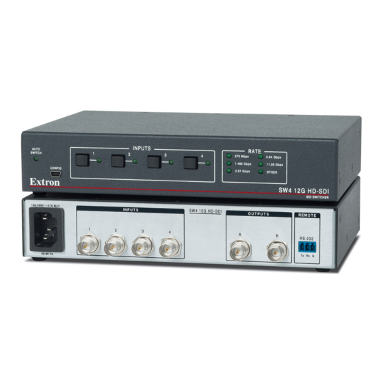
Rear Panel Features
A
100-240V
0.1A MAX
1
50-60Hz
AC power connector
A
Input connectors
B
Figure 1.
Rear Panel
Installation
1.
Turn off all of the equipment and disconnect it from the power source.
2.
(Optional) Mount the switcher on top of a flat surface using the provided rubber feet, under a table using an optional
under‑desk mounting kit, or to a rack shelf using an optional rack shelf‑mounting kit (kits are available at www.extron.com).
3.
Connect up to four SDI, HD‑SDI, or 3G‑SDI video inputs to BNC input connectors 1 through 4 (see figure 1,
NOTE:
Each input is equalized regardless of the rate.
4.
Connect one or two video SDI, HD‑SDI, or 3G‑SDI output devices to the rear panel female BNC buffered output connectors
(
).
C
NOTE:
Mirrored outputs 1 and 2 output identical signals.
5.
If the switcher will be connected to a computer or host controller for remote
configuration and control, do either of the following:
Wire the provided 3‑pole captive screw connector to an RS‑232 cable.
•
Connect the RS‑232 cable to the RS‑232 port on the rear panel of
the switcher and to the host RS‑232 port (see the illustration at right).
Protocol for the RS‑232 port is 9600 baud, 8 data bits, 1 stop bit, no
parity.
Connect a USB A to mini B cable from the computer to the front panel
•
USB Config port (see
6.
Power on the input and output devices, then connect power to the switcher
by connecting the provided IEC power cord to the switcher power connector
(see figure 1,
) and to an AC outlet.
A
For information on safety guidelines, regulatory compliances, EMI/EMF compatibility, accessibility, and related topics, see the
Extron Safety and Regulatory Compliance Guide
B
SW4 12G HD-SDI
INPUTS
2
3
4
Output connectors
C
RS‑232 control connector
D
figure
2,
B
, on the next page).
on the Extron website.
C
D
OUTPUTS
REMOTE
A
B
RS-232
Tx
Rx
G
Switcher
RS-232
Tx Rx
B
).
Computer
5
1
9
6
DB9 connector (female)
pinout to control equipment
Pin
RS-232
Function
1
—
—
2
Rx
Receive data (+)
3
Tx
Transmit data (–)
4
—
—
5
Gnd
Signal ground
6
—
—
7
—
—
8
—
—
9
—
—
1
Advertisement

Related Manuals for Extron electronics SW4 12G HD-SDI


Summary of Contents for Extron electronics SW4 12G HD-SDI
-
Page 1: Rear Panel Features
The SW4 12G HD‑SDI has front panel, RS‑232, USB, and auto‑input switching control options. NOTE: For full installation, configuration, menus, connector wiring, and operation details, see the SW4 12G HD-SDI User Guide at www.extron.com. Rear Panel Features... -
Page 2: Front Panel Features
The illustration at right shows an example of how the SW4 12G HD‑SDI switcher Projector can be connected. 68-3187-50 Rev. A © 2018 Extron Electronics — All rights reserved. All trademarks mentioned are the property of their respective owners. www.extron.com 09 18...
Need help?
Do you have a question about the SW4 12G HD-SDI and is the answer not in the manual?
Questions and answers