Table of Contents
Advertisement
Quick Links
Download this manual
See also:
User Manual
Tel +1 (717) 767-6511
Fax +1 (717) 764-0839
www.redlion.net
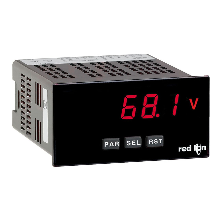
MODEL PAXLA - PAX LITE DC VOLT/CURRENT/PROCESS METER
U L
C C
US LISTED
US LISTED
R
IND. CONT. EQ.
51EB
For Model No. PAXLA0U0 Only
GENERAL DESCRIPTION
The PAXLA is a versatile meter available as a DC volt, current, or process
meter with scaling and dual Form C relay outputs. The meter is programmed
through the front panel buttons and the use of jumpers. The RST Key will also
function as a front panel display reset.
Once the front panel programming is complete, the buttons can be disabled
by a user input setting. The meter has been specifically designed for harsh
industrial environments. With a NEMA 4X/IP65 sealed bezel and extensive
testing to meet CE requirements, the meter provides a tough yet reliable
application solution.
SAFETY SUMMARY
All safety regulations, local codes and instructions that appear in this and
corresponding literature, or on equipment, must be observed to ensure personal
safety and to prevent damage to either the instrument or equipment connected to
it. If equipment is used in a manner not specified by the manufacturer, the
protection provided by the equipment may be impaired.
CAUTION: Risk of Danger.
Read complete instructions prior to
installation and operation of the unit.
ORDERING INFORMATION
MODEL NO. DESCRIPTION
Volt/Current/Process Meter with Dual Relay Output
PAXLA
UL Listed Volt/Current/Process Meter with Dual
Relay Output
PAXLBK
Unit Label Kit Accessory
DIMENSIONS In inches (mm)
8. 8 . 8 . 8 . 8
MA
X
I M N
S 1
P
S 2
P
PAR
SEL
RST
3.80
(96.5)
CAUTION: Risk of electric shock.
PART NUMBER
PAXLA000
PAXLA0U0
PAXLBK10
V
1.95
(49.5)
.10
(2.5)
5 DIGIT, 0.56" HIGH RED LED DISPLAY
PROGRAMMABLE SCALING AND DECIMAL POINTS
PROGRAMMABLE USER INPUT
DUAL 5 AMP FORM C RELAY
UNIVERSALLY POWERED
NEMA 4X/IP65 SEALED FRONT BEZEL
OPTIONAL CUSTOM UNIT OVERLAY W/ BACKLIGHT
MINIMUM AND MAXIMUM DISPLAY CAPTURE
SPECIFICATIONS
1. DISPLAY: 5 digit, 0.56" (14.2 mm) intensity adjustable Red LED (-19999 to
99999)
2. POWER REQUIREMENTS:
AC POWER: 50 to 250 VAC 50/60 Hz, 12 VA
Isolation: 2300 Vrms for 1 min. to all inputs and outputs
DC POWER: 21.6 to 250 VDC, 6 W
DC Out: +24 VDC @ 100 mA if input voltage is greater than 50 VAC/VDC
+24 VDC @ 50 mA if input voltage is less than 50 VDC
3. INPUT RANGES: Jumper Selectable
D.C. Voltages: 200 mV, 2 V, 20 V, 200 V, 10 V
ACCURACY @
INPUT
°
23
C LESS
RANGE
THAN 85% RH
200 mV
0.1% of span
2 V
0.1% of span
20 V
0.1% of span
200 V
0.1% of span
10 V
0.1% of span
D.C. Currents: 200 A, 2 mA, 20 mA, 200 mA
ACCURACY @
INPUT
°
23
C LESS
RANGE
THAN 85% RH
200
0.1% of span
2 mA
0.1% of span
20 mA
0.1% of span
200 mA
0.1% of span
D.C. Process: 4 to 20 mA, 1 to 5 VDC, 0/1 to 10 VDC
INPUT RANGE
4 - 20 mA
Use the 20 mA range
1 - 5 VDC
Use the 10V range
1 - 10 VDC
Use the 10V range
4. OVERRANGE/UNDERRANGE INDICATION:
Input Overrange Indication: "
Input Underrange Indication: "
Display Overrange/Underrange Indication: "
5. A/D CONVERTER: 16 bit resolution
6. UPDATE RATES:
A/D conversion rate: 20 readings/sec.
Display update: 500 msec min.
1.75
(44.5)
4.10
(104.1)
1
Bulletin No. PAXLA-B
Drawing No. LP0722
Released 04/09
MAX
INPUT
INPUT
RESOLUTION
IMPEDANCE
SIGNAL
1.033 M
75 VDC
10
V
75 VDC
0.1 mV
1.033 M
250 VDC
1 mV
1.033 M
250 VDC
10 mV
1.033 M
538 K
75 V
1 mV
MAX
INPUT
INPUT
RESOLUTION
IMPEDANCE
SIGNAL
1.111 K
15 mA
10 nA
111
0.1 A
50 mA
11
1 A
150 mA
1
10 A
500 mA
SELECT RANGE
".
".
.....
.....
"/"-
1
2
3
4
5
6 7
8
9
10
11 12
13
14 15
3.60 (91.4)
TEMP.
COEFFICIENT
70 ppm /°C
70 ppm /°C
70 ppm /°C
70 ppm /°C
70 ppm /°C
TEMP.
COEFFICIENT
70 ppm /°C
70 ppm /°C
70 ppm /°C
70 ppm /°C
"
Advertisement
Table of Contents

Related Manuals for red lion PAXLA


Summary of Contents for red lion PAXLA
- Page 1 GENERAL DESCRIPTION SPECIFICATIONS The PAXLA is a versatile meter available as a DC volt, current, or process 1. DISPLAY: 5 digit, 0.56" (14.2 mm) intensity adjustable Red LED (-19999 to meter with scaling and dual Form C relay outputs. The meter is programmed 99999) through the front panel buttons and the use of jumpers.
-
Page 2: Installation
7. USER INPUT: 13. CERTIFICATIONS AND COMPLIANCES: SAFETY User Input: Software selectable pull-up (24.7 K) or pull-down resistor Type 4X Enclosure rating (Face only), UL50 (20 K) that determines active high or active low input logic. IEC 61010-1, EN 61010-1: Safety requirements for electrical equipment Trigger levels: V = 1.0 V max;... -
Page 3: Setting The Jumpers
2.0 S ETTING THE UMPERS INPUT RANGE JUMPER FRONT DISPLAY This jumper is used to select the proper input range. The input range selected in programming must match the jumper setting. Select a range that is high enough to accommodate the maximum signal input to avoid overloads. To access the jumpers, remove the meter base from the case by firmly Main squeezing and pulling back on the side rear finger tabs. -
Page 4: Power Wiring
3.1 POWER WIRING DC Out Power Power + EXC Terminal 3: + 24 VDC OUT Terminal 1: VAC/DC + Terminal 4: Common Terminal 2: VAC/DC - COMM 3.2 USER INPUT WIRING Sinking Logic Sourcing Logic Terminal 8: User Input USER USER Terminal 9: User Comm USER COMM... - Page 5 4.0 R EVIEWING THE RONT UTTONS AND ISPLAY Display 8. 8 . 8 . 8 . 8 Readout Optional Custom Legends* Units Overlay Setpoint Alarm Annunciators BUTTON DISPLAY MODE OPERATION PROGRAMMING MODE OPERATION Access Programming Mode Store selected parameter and index to next parameter Advance through selection list/select digit position in Index display through selected displays parameter value...
- Page 6 5.1 MODULE 1 - S IGNAL NPUT ARAMETERS 1-INP PARAMETER MENU rANGE INP 1 dSP 1 INP 2 dSP 2 USrIN U-ASN U-Act dECPt OFSEt FILtr bANd StYLE Input Display Display Filter Input Value Display Value Input Value Display Value User Input User Input User Input...
- Page 7 For most applications, recalibration every 1 to 2 years should be sufficient. Calibration of the PAXLA involves a calibration which should only be performed by individuals experienced in calibrating electronic equipment. Allow 30 minute warm up before performing any calibration related procedure.
- Page 8 1. Connect a precision DC voltage source with an accuracy of 0.01% or better of 0.01% or better to the COMM terminal. Leave the positive lead of the DC to the volt input and COMM terminals of the PAXLA. Set the output of the current source unconnected.
- Page 9 PROGRAMMING SECURITY CODE USER INPUT USER INPUT SECURITY MODE WHEN “PAR” FULL PROGRAMMING FUNCTION STATE CODE BUTTON IS PRESSED MODE ACCESS Full Programming Immediate Access After Quick Programming 1-99 Quick Programming with correct code entry ...
- Page 10 ON TIME DELAY OUTPUT RESET WITH DISPLAY RESET Enter the time value in seconds that the output is delayed from turning on This parameter enables the button or user input to reset the output when after the trigger point is reached.
- Page 11 PAXLA PROGRAMMING QUICK OVERVIEW...
- Page 12 The Company disclaims all liability for any affirmation, promise or representation with respect to the products. The customer agrees to hold Red Lion Controls harmless from, defend, and indemnify RLC against damages, claims, and expenses arising out of subsequent sales of RLC products or products...
Need help?
Do you have a question about the PAXLA and is the answer not in the manual?
Questions and answers