Table of Contents
Advertisement
Quick Links
PERFORMANCE PLUS™
100 GPD Ultra-High Efficiency RO/DI
(MC-RODI-100-PPLUS)
OWNER'S MANUAL
&
INSTALLATION INSTRUCTIONS
WARNING
Please read carefully before proceeding with installation. Failure
to follow any attached instructions or operating parameter may
lead to the product's failure and possible damage to property.
2017-10-25
Advertisement
Table of Contents

Subscribe to Our Youtube Channel
Related Manuals for SpectraPure PERFORMANCE PLUS MC-RODI-100-PPLUS


Summary of Contents for SpectraPure PERFORMANCE PLUS MC-RODI-100-PPLUS
- Page 1 PERFORMANCE PLUS™ 100 GPD Ultra-High Efficiency RO/DI (MC-RODI-100-PPLUS) OWNER’S MANUAL & INSTALLATION INSTRUCTIONS WARNING Please read carefully before proceeding with installation. Failure to follow any attached instructions or operating parameter may lead to the product’s failure and possible damage to property. 2017-10-25...
-
Page 2: Table Of Contents
Thank You for your purchase of a SpectraPure System. With proper installation and maintenance, this system will ® provide you with high quality water for years to come. All SpectraPure products are rigorously tested by us for ® safety and reliability. If you have any questions or concerns, please contact our customer service department at 1.800.685.2783 or refer to our online troubleshooting at www.spectrapure.com. -
Page 3: Operational Specifications
- (1) UHE Module (1) Safety Backup Float IF ANY OF THE ITEMS LISTED ABOVE ARE MISSING PLEASE CONTACT SPECTRAPURE PRIOR TO INSTALLATION. ALL RETURNS WITHOUT RMA# WILL BE REFUSED. CLAIMS MUST BE WITHIN 10 DAYS FROM RECEIPT. Float Switch... -
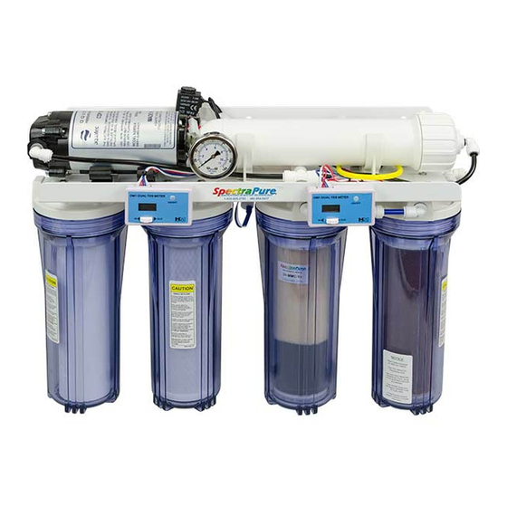
Page 4: Front View (Components)
SpectraPure ® FRONT VIEW (COMPONENTS) Pressure SpectraSelectPlus™ Recirculation Gauge 90 GPD Membrane Pump (inside housing) Left-Hand TDS Meter Right-Hand TDS Meter “IN”= Tap Water TDS “IN”= Mega MaxCap DI TDS “OUT”= RO TDS “OUT”= Enduro DI TDS Enduro DI™ 0.5 Micron Cartridge MicroTek™... -
Page 5: Uhe Control Module
SpectraPure ® UHE CONTROL MODULE ELECTRICAL CONNECTIONS Floats - Red/White/Black (3 sockets) Flush Solenoid - Red/Red (2 sockets) Pump Connection - Black/Red (2 sockets) Input Solenoid - White /White (2 sockets) Power Transformer - Black Barrel LED SEQUENCES Input Solenoid LED - Lights when system turns on. -
Page 6: System Diagram
SpectraPure ® SpectraPure Inc. ® 480.894.5437 Call us toll-free 1.800.685.2783 2167 East Fifth St, Tempe, Arizona 85281... -
Page 7: Triple -Probe Tds Meter
SpectraPure ® DUAL-PROBE TDS METERS The Performance Plus™ UHE system comes equipped with two (2) dual -probe TDS meters. Use the selector switch on the meter to read the TDS from each of the probes. The readings from the Left-Hand Meter will be used to monitor the quality (percentage of rejection) of the RO membrane. -
Page 8: Preparation
SpectraPure ® PREPARATION 1. CHOOSING THE BEST MOUNTING LOCATION: LIGHT SOURCE: Algae is more likely to thrive inside clear housings when exposed to ultraviolet light and other sources like metal halide lighting. Avoid installing the unit in bright light or direct sunlight. -
Page 9: Setup Procedures
SpectraPure ® SETUP PROCEDURES STEP 1: INSTALLATION OF THE HIGH & LOW FLOAT SWITCHES: A. Install both the High and Low Floats onto an open container, such as a Rubbermaid trash can. The floats ® can be mounted by drilling a 5/8" hole. The white washer should be located on the inside of the reservoir. -
Page 10: Installing The Float Valve
SpectraPure ® SETUP PROCEDURES (continued) STEP 3: INSTALL THE FLOAT VALVE near the top of the reservoir. This will act as a fill valve and as a safety backup float. The Float Valve should be mounted higher than the High Float and offset to one side so that it does not interfere with the High Float when the reservoir is being filled. -
Page 11: Final Connections
SpectraPure ® SETUP PROCEDURES (continued) STEP 5: Direct the waste line (yellow) to a drain or connect it permanently to a drain pipe via a Drain Saddle. (Drain Saddle is not included with system.) CAUTION An extremely long drain line may cause excessive back pressure on the system. For drain lines longer than 10 feet, 3/8"... -
Page 12: Erratic Operation Warning
SpectraPure ® SETUP PROCEDURES (continued) ERRATIC OPERATION Erratic operation can almost always be determined to be caused by the electric floats or the wires connecting them to the control module. Here is a test to determine if the problem lies with the floats or the control module. Disconnect the 3 pin cable to the floats at the control module. -
Page 13: Maintenance Procedures
SpectraPure ® MAINTENANCE PROCEDURES Maintenance and troubleshooting procedures have been made easy and effective with a combination of the two dual- probe TDS meters and a built-in pressure gauge. It is recommended that you keep replacement cartridges on hand, ready to install as soon as the monitor indicates that the cartridge in use is exhausted. -
Page 14: Carbon Block Prefilter Replacement
SpectraPure ® MAINTENANCE PROCEDURES (continued) CARBON BLOCK PREFILTER REPLACEMENT For maximum contaminant removal and long membrane life, the Carbon prefilter must be changed when the Chlorine Test Kit shows more than 0.1ppm of chlorine in the waste water stream. Materials Required: 0.5 micron Carbon Block Filter (CF-0.5-10), Filter Wrench, Chlorine Test Kit (TK- CL-10 - KIT) Procedure: (SECOND FILTER ON LEFT WHEN FACING SYSTEM) 1. -
Page 15: Reverse Osmosis Membrane Production Calculation
SpectraPure ® MAINTENANCE PROCEDURES (continued) REVERSE OSMOSIS MEMBRANE PRODUCTION CALCULATION Actual production of a membrane is dependent on two factors: Tap Water Pressure and Tap Water Temperature. In order to characterize a membrane, there must be common testing data. Industry standards for testing membrane performance are: 60 PSI tap water pressure and 77°... -
Page 16: Reverse Osmosis Membrane Replacement
SpectraPure ® MAINTENANCE PROCEDURES (continued) REVERSE OSMOSIS MEMBRANE REPLACEMENT 1. Turn off the water supply to the RO system and unplug the transformer. Place the system where the membrane housing is easily accessible. 2. Remove the black tubing from the membrane feed push fitting by depressing the collar on the fitting with your thumb and pulling the tubing from the push fitting. -
Page 17: Deionization Cartridge Maintenance And Replacement
SpectraPure ® MAINTENANCE PROCEDURES (continued) DEIONIZATION CARTRIDGE MAINTENANCE AND REPLACEMENT The Performance Plus™ uses two DI stages. The Mega MaxCap DI™ cartridge is located upstream of the Enduro DI™ cartridge and acts as a “roughing” stage by removing the vast majority of residual ammonia, phosphates, and other trace ionized impurities that have passed through the system’s RO membrane. -
Page 18: Troubleshooting Guide
SpectraPure ® TROUBLE SHOOTING GUIDE LOW PRODUCTION RATE. a. Plugged prefilters. i. Replace prefilters. b. Low water temperature. ii. Use higher GPD membrane. c. Fouled membrane. iii. Replace membrane. d. Plugged flow restrictor. iv. Replace flow restrictor & membrane. ZERO PRODUCTION RATE. -
Page 19: Warranty Information
® workmanship for a period of three years from the date of receipt. SpectraPure’s liability under this warranty shall be limited to repairing or replacing at SpectraPure’s option, without charge, F.O.B. SpectraPure’s factory, any product of SpectraPure’s manufacture. -
Page 20: Replacement And Upgrade Parts List
SpectraPure ® REPLACEMENT PARTS Catalog No. Replacement Part Description SF-MT-0.5 -10 0.5 Micron Sediment Filter 1st Stage CF-0.5 -10 0.5 Micron Carbon PreFilter 2nd Stage MEM-SP-0090 SpectraSelectPlus™ RO Membrane 3rd Stage DI-MMC-10 Mega MaxCap DI™ Deionization Cartridge 4th Stage DI -ENDI-10 Enduro DI™...
Need help?
Do you have a question about the PERFORMANCE PLUS MC-RODI-100-PPLUS and is the answer not in the manual?
Questions and answers