Table of Contents
Advertisement
Quick Links
Advertisement
Table of Contents

Related Manuals for Burkert 8139


Summary of Contents for Burkert 8139
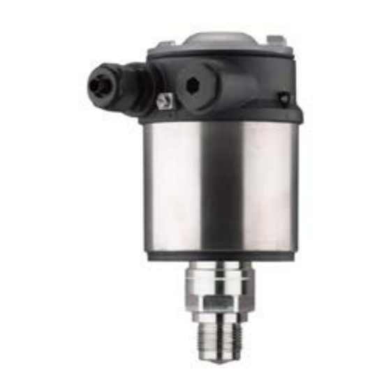
- Page 1 Quick setup guide LEVEL TRANSMITTER 8139 4 … 20 mA/HART - two-wire...
-
Page 2: Table Of Contents
Operating Instructions Manual as well as the Safety Manual that comes with instruments with SIL qualification. These manuals are available on our homepage. Operating instructions LEVEL TRANSMITTER 8139 - 4 … 20 mA/HART - Two-wire: Document-ID 58499 Editing status of the quick setup guide: 2019-04-16 LEVEL TRANSMITTER 8139 • 4 … 20 mA/HART - two-wire... -
Page 3: For Your Safety
During work on and with the device, the required personal protective equipment must always be worn. Appropriate use LEVEL TRANSMITTER 8139 is a sensor for continuous level meas- urement. You can find detailed information about the area of application in chapter "Product description". Operational reliability is ensured only if the instrument is properly used according to the specifications in the operating instructions manual as well as possible supplementary instructions. -
Page 4: Eu Conformity
G1½ or 1½ NPT thread with integrated horn antenna. • The mounting location must be at least 4 km away from radio astronomy stations, unless special permission was granted by the responsible national approval authority LEVEL TRANSMITTER 8139 • 4 … 20 mA/HART - two-wire... - Page 5 1 For your safety • When installed within 4 to 40 km of a radio astronomy station, the instrument must not be mounted higher than 15 m above the ground. You can find a list of the respective radio astronomy stations in chap- ter "Supplement". LEVEL TRANSMITTER 8139 • 4 … 20 mA/HART - two-wire...
-
Page 6: Product Description
10 Reminder to observe the instrument documentation Scope of this operating This operating instructions manual applies to the following instrument instructions versions: • Hardware version from 1.0.3 • Software version from 1.3.1 LEVEL TRANSMITTER 8139 • 4 … 20 mA/HART - two-wire... -
Page 7: Mounting
Depending on the selected variant, the sensor can be rotated in the strap: • Single chamber housing – Angle of inclination in three steps 0°, 90° and 180° – Angle of inclination 180°, infinitely variable Fig. 3: Adjustment of the angle of inclination LEVEL TRANSMITTER 8139 • 4 … 20 mA/HART - two-wire... -
Page 8: Mounting Instructions
(see chapter "Setup"). If you cannot maintain this distance, you should carry out a false signal suppression during setup. This applies particularly if buildup on the vessel wall is expected. In such cases, we recommend repeating the false signal suppression at a later date with existing buildup. LEVEL TRANSMITTER 8139 • 4 … 20 mA/HART - two-wire... - Page 9 In vessels with conical bottom it can be advantageous to mount the sensor in the centre of the vessel, as measurement is then possible down to the bottom. Fig. 7: Mounting of the radar sensor on vessels with conical bottom LEVEL TRANSMITTER 8139 • 4 … 20 mA/HART - two-wire...
-
Page 10: Connecting To Power Supply
6. Insert the wire ends into the terminals according to the wiring plan Information: Solid cores as well as flexible cores with wire end sleeves are insert- ed directly into the terminal openings. In case of flexible cores without end sleeves, press the terminal from above with a small screwdriver, the terminal opening is then free. When the screwdriver is released, the terminal closes again. LEVEL TRANSMITTER 8139 • 4 … 20 mA/HART - two-wire... -
Page 11: Wiring Plan, Single Chamber Housing
Fig. 9: Electronics and connection compartment - single chamber housing Voltage supply, signal output For display and adjustment module or interface adapter For external display and adjustment unit Ground terminal for connection of the cable screening LEVEL TRANSMITTER 8139 • 4 … 20 mA/HART - two-wire... -
Page 12: Set Up With The Display And Adjustment Module
Fig. 10: Insertion of the display and adjustment module with single chamber housing Note: If you intend to retrofit the instrument with a display and adjustment module for continuous measured value indication, a higher lid with an inspection glass is required. LEVEL TRANSMITTER 8139 • 4 … 20 mA/HART - two-wire... -
Page 13: Parameter Adjustment - Quick Setup
In this menu item you specify the for of the vessel bottom and top. 5. Vessel height/Measuring range In this menu item you enter the height of the vessel and hence the active measuring range. LEVEL TRANSMITTER 8139 • 4 … 20 mA/HART - two-wire... -
Page 14: Menu Overview
Storage tank Vessel form Vessel top Dished form Vessel bottom Dished form Vessel height/ 35 m Measuring range Max. adjustment 0,000 m(d) 100.00 % Min. adjustment 35 m 0.00 % LEVEL TRANSMITTER 8139 • 4 … 20 mA/HART - two-wire... - Page 15 Menu item Default setting Instrument units Distance in m Temperature in °C False signal suppres- sion Linearization Linear Date/Time Actual date/Actual time Reset HART mode Address 0 Copy instrument set- tings LEVEL TRANSMITTER 8139 • 4 … 20 mA/HART - two-wire...
- Page 16 5 Set up with the display and adjustment module Info Menu item Parameter Device name LEVEL TRANSMITTER 8139 Instrument version Hardware and software version Date of manufacture Date Instrument features Order-specific characteristics LEVEL TRANSMITTER 8139 • 4 … 20 mA/HART - two-wire...
-
Page 17: Supplement
Ʋ for 12 V < U < 18 V ≤ 0.7 V (16 … 400 Hz) Ʋ for 18 V < U < 35 V ≤ 1 V (16 … 400 Hz) Load resistor Ʋ Calculation )/0.022 A Ʋ Example - U = 24 V DC (24 V - 12 V)/0.022 A = 545 Ω LEVEL TRANSMITTER 8139 • 4 … 20 mA/HART - two-wire... - Page 18 Notes LEVEL TRANSMITTER 8139 • 4 … 20 mA/HART - two-wire...
- Page 19 Notes LEVEL TRANSMITTER 8139 • 4 … 20 mA/HART - two-wire...
- Page 20 The smart choice of Fluid Control Systems www.burkert.com 61579-EN-190416...
Need help?
Do you have a question about the 8139 and is the answer not in the manual?
Questions and answers