
Related Manuals for Burkert 8175


Summary of Contents for Burkert 8175
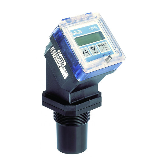
- Page 1 TYPES 8175 / 8170 ULTRASONIC LEVEL TRANSMITTER COMPACT AND SEPARATE VERSIONS Instruction Manual Ident. 427998P...
-
Page 2: Table Of Contents
Electronic card identification ........................12 General Electrical Connection 3.4.1 18-32 VDC Wiring via a cable plug ....................13 3.4.2 8175 Compact version,18-32VDC or 115/230VAC ................. 14 3.4.3 8175 Panel version,18-32VDC ....................... 16 3.4.4 8175 Wall mounted version, 18-32VDC ..................17 Easy Link Connections ........................... -
Page 3: Introduction
Indicates information about repairs, service, maintenance and spare parts. GENERAL SAFETY INSTRUCTIONS Congratulations on purchasing our 8175 Digital Level Transmitter. Before installing or using this product, please read this manual and any other relevant documentation to ensure you fully benefit from all the advantages the product can offer. -
Page 4: Quickstart
QUICKSTART This section provides a comprehensive installation and operation guide which will assist with the commissioning of the 8175 Level Transmitter. INSTALLATION Verification of items received Unpacking See section 6.5 Verify See section 6.7 Ident. No. Contact your local Bürkert subsidiary. - Page 5 QUICKSTART PROGRAMMING The electronics within the 8175 ultrasonic level transmitter allows the unit to be configurated as either distance, level or volume depending on the application. To access the CALIBRATION MENU simutaneously press ENTER for 5 seconds. The ‘Enter‘ key can be locked to avoid accidental or unauthorised access - section 3.3.
-
Page 6: Level
20mA -> 8.50 m Configure relays See section 4.4.8 1 & 2 ( if available ) Measurement or Simulation (optional) See section 2.3 The actions which are highlighted in grey must be fully completed for accurate measurement. 8175... -
Page 7: Volume
See section 4.4.7 output range Configure relays See section 4.4.8 1 & 2 ( if available ) Measurement or Simulation (optional) See the next page. The actions which are highlighted in grey must be fully completed for accurate measurement. 8175... -
Page 8: Testing
See section 4.5.4 signal strength the highest signal strength. This is optional although it is Simulation of See section 4.5.5 recommended for the outputs commissioning large systems. Reseting of the See section 4.5.6 stored parameters The unit is now ready 8175... -
Page 9: General Installation Guidelines
INSTALLATION GENERAL INSTALLATION GUIDELINES Prior to the installation of the 8175 ultrasonic level transmitter, a clear mounting location for the product must be determined. The level transmitter or sensor types 8175 / 8170 are designed for liquid level measurement. It is the user responsability to test the functionality of the device for any other material such as powders, granuals etc. -
Page 10: Installation
Be careful not to overtighten the transmitter in the fitting. Shaft mounting If the transmitter or sensor 8175 is installed on a shaft, it must not be higher than 400 mm for a diameter of 100 mm, or 250 mm for a diameter of 80 mm. -
Page 11: Panel Version Installation
, tightening the locking washers 3.2.2 WALL-MOUNTED VERSION INSTALLATION The level transmitter in a wall-mounted version has 4 fixing holes at the corners of the enclosure. Remove the white blanking strips and the cover to access to fixing holes 8175... -
Page 12: Electronic Card Identification
INSTALLATION ELECTRONIC CARD IDENTIFICATION This section allows easy identification of the features and electrical connections within the 8175 level transmitter depending on the version. 18-32VDC ELECTRONIC CARD Terminal connections - SW 2 - Sourcing or Connection of power supply sinking configuration. -
Page 13: General Electrical Connection
3. Connect the transmitter according to the pin assignment in Fig. 3.4 4. When re-assembling, the internal part can be rotated in 90°steps to a desired position before inserting back into the casing 8175... -
Page 14: 8175 Compact Version,18-32Vdc Or 115/230Vac
PG 13.5 and wire according to one of the pin assignment diagrams below. The electronics within the 8175 allows a sourcing or sinking PLC to be connected. Position A (Fig 3.5) provides a sourcing configuration and Position B (Fig 3.6) a sinking configuration. - Page 15 PG 13.5 and wire according to one of the pin assignment diagrams below. The electronics within the 8175 allows a sourcing or sinking PLC to be connected. Position A (Fig 3.5) provides a sourcing configuration and Position B (Fig 3.6) a sinking configuration.
-
Page 16: 8175 Panel Version,18-32Vdc
Open the cabinet/cupboard and wire according to the pin assignment diagrams below. The electronics within the 8175 allows a sourcing or sinking PLC to be connected. Position A (Fig 3.11) provides a sourcing configuration and Position B (Fig 3.12) a sinking configuration. -
Page 17: 8175 Wall Mounted Version 18-32Vdc
The ‘Enter‘ key can be locked by placing the SW 1 swich into the up position to avoid accidental or unauthorided access. 3.4.4 8175 WALL MOUNTED VERSION 18-32VDC CONNECTION OF THE 8170 SENSOR Remove the cover via the screws on the front display and remove the PG 9 as indicated passing the cable through the hole. - Page 18 PG 9 and wire according to one of the pin assignment diagrams below. The electronics within the 8175 allows a sourcing or sinking PLC to be connected. Position A (Fig 3.15) provides a sourcing configuration and Position B (Fig 3.16) a sinking configuration.
-
Page 19: Easy Link Connections
EASY LINK / NETWORKING CONNECTIONS CONTINUOUS PNEUMATIC LEVEL CONTROL 8175 24 V= Jumper Jumper Example of LINK between the 8175 level transmitter 18-32VDC and the 8630 Top Control mounted on a diaphragm valve type 2031. NETWORKING provided by the relay outputs 8175... - Page 20 CONTINUOUS PNEUMATIC LEVEL CONTROL 24 V= 4-20 mA 8175 POSITIONER TYPE 1067 Example of LINK between the 8175 level transmitter 18-32VDC and the 1067 positioner mounted on an angle seat valve type 2632. NETWORKING provided by the relay outputs. 8175...
- Page 21 INSTALLATION CONTINUOUS SOLENOID LEVEL CONTROL 24 V= 4-20 mA 8175 PT1000 Alarm Example of LINK between the 8175 level transmitter 18-32VDC and the 8624 solenoid valve with PI controller. NETWORKING provided by the relay outputs. 8175...
- Page 22 4-20 mA 8175 Top Control on/off Example of LINK between the 8175 level transmitter 18-32VDC and the 8631 Top Control on/off mounted on a diaphragm valve type 2031 and pilot valve type 6012. NETWORKING provided by the 4-20mA output 8175...
-
Page 23: Operating And Control Guide
Access to the CALIBRATION MENU* 5 Seconds ENTER Access to the TEST MENU* 0..9 5 Seconds * Only available within the main menu. ENTER Key can be locked to avoid accidental or unauthorised access. For further information see section 3.3. 8175... -
Page 24: Menu Guide
OPERATION MENU GUIDE The menu guide below will assist in quickly and easily finding a desired parameter and programming the 8175 ultrasonic level transmitter. MAIN MENU 1.455 M ENTER 0..9 0..9 24.2 °C ENTER 0..9 16.45 A TEST MENU CALIBRATION MENU LANGUAGE 0..9... -
Page 25: Main Menu
(Range 4.00mA to 20.00mA with a 22mA error signal). The units will blink while the transmitter is performing an internal calculation. The whole display will blink when the signal has been lost or in cases of an electronic failure. 8175... -
Page 26: Calibration Menu
Parameter definition of relays 1 & 2 for 4.4.8 level, distance or volume, T° and/or failure alarm. Back to the operation mode; store the new parameters set. The following sections explain how to change the parameter values within the calibration menu above. 8175... -
Page 27: Language
Volume Teach-In. SELECTED MEASURING UNITS UNITS USED FOR TEACH-IN DISTANCE/LEVEL VOLUME DISTANCE VOLUME US/Imp gal NOT VALID US/Imp gal NOT VALID inch NOT VALID foot NOT VALID inch foot inch US/Imp gal US/Imp gal foot US/Imp gal US/Imp gal 8175... - Page 28 US. GAL VOLUME IMP. GAL DEC PT 0 DEC PT 1 DEC PT 2 FILTER DEC PT3 The level, distance or volume can be displayed with 0, 1, 2 or 3 decimal places but 4 digits will always be displayed. 8175...
-
Page 29: Filter Function
Choose the filter with a maximum speed change superior to that of your process. The diagrams below display the relationship between the actual signal and the level of filtering. Filters 6 and 2 Max. Speed Filters 0 and 3 change Damping Filter 9 Damping Max. Speed change 8175... - Page 30 With the 8175 level transmitter it is additionally important to select the type of filter depending on the application. In some cases where a vessel is closed, echoes can be rebounded from the top of the vessel producing a ‘doubling’...
-
Page 31: Gas Characteristics
CALIBRATION MENU 4.4.4 GAS CHARACTERISTICS In order for the 8175 level transmitter to find a precise measure of the level, the characteristics of gas between the liquid and transmitter have to be defined. If this value is not known either a default value can be applied or the characteristics can be calculated by performing a 2 point Teach-In. -
Page 32: Echo Filtering
To assist with the completion of this function a schematical diagram is displayed in the next page. The echo identified and stored by this procedure can be erased by the reset function within the test menu ( interference table) - section 4.5.6. 8175... - Page 33 TEACH-IN ENTER 1 = 5.10 M ENTER VALID N TEACH-IN ENTER 2= 4.80 M 0..9 Validate and save parameters defined. N = 4.50 M Select the echo of the target level TEACH-IN VALID Y ENTER ERROR ENTER VALID N 8175...
-
Page 34: Teach-In Procedures
TEACH N TEACH-IN CURRENT ENTER and advance to the next option. 1 or 2 point Level or TEACH Y ENTER 0..9 distance Teach-In procedure RESET ENTER Reset the distance reference point (Reset is not displayed if configured as level) 8175... -
Page 35: Or 2 Point Level Or Distance Teach-In Procedure
Enter the distance in the appropriate units and the transmitter will automatically calculate the difference between the distance entered and actual distance measured for a second time. (approx. 3 seconds). Select ‘VALID Y‘ to validate the option or ignore and advance to the next parameter. 8175... -
Page 36: Reseting Of The Distance Reference Point
‘default‘ reference point - the base of the sensor. On recieving the transmitter the reference point will be configured as the base of the sensor. RESET VALID Y ENTER 0..9 VALID N ENTER CURRENT 8175... -
Page 37: Teach-In For Volume
The option ‘SPECIAL‘ allows the user to select the previous volume Teach-In procedure completed. This procedure allows the transmitter to compute the volume of the liquid contained in the tank/vessel according to the measured level of the fluid. 8175... - Page 38 VER. CYL X=00.00 0..9 X=01.20 ENTER Y=00.00 Z=00.00 CUBE 0..9 0..9 Y=01.30 ENTER Z=01.65 ENTER 0..9 SPHERE X=00.00 0..9 X=01.65 ENTER MANUAL SPECIAL 0000 L 0..9 1.36 M ENTER 0000 L VALID Y CURRENT ENTER VALID N CURRENT ENTER 8175...
-
Page 39: Manual Input Of Distances And Associated Volumes
‘END YES‘ and select to validate the option or ignore and advance to the next function. Alternatively it is possible to continue and enter a distance measurement and associated volume by selecting ‘END NO‘ when the option appears. This can be repeated to enter a total of 12 measurements. 8175... - Page 40 This option enables to display volume in a percentage for example or in alternative units. The units selected must then not be taken into account. In the same way, the 8175 can be used to display the flow rate within open channels. 8175...
-
Page 41: Volume Teach-In Procedure
‘END YES‘ and select ‘VALID Y‘ to validate the option or ignore and advance to the next function. Alternatively it is possible to continue and enter associated volumes by selecting ‘END NO‘ . This can be repeated to enter a total of 12 measurements. 8175... - Page 42 Second distance measurement Enter the 2 Volume 0..9 2=0035. 2 ENTER ENTER VALID Y CURRENT ENTER END YES ENTER VALID N CURRENT 0..9 ENTER END NO 02.65 M ENTER N=0000. 0 Enter the distance measurement Volume 0..9 ENTER N=0100.1 8175...
-
Page 43: Output Current
Enter the end of the measuring range 0..9 ENTER RELAY 20=12.00 In case of signal loss the device will emit an error signal of 22mA. The diagram below shows the type of relationship between the 4-20mA ouptut and the associated measuring range. 8175... -
Page 44: Relay (Option)
Relay 2 : Inverted with thresholds of 6 and 8 m and delay of 2 Sec. 1- and 2- = the low settings for both relays 1+ and 2+ = the high settings for both relays contact t/ s Relay 1 Relay 2 DEL/VERZ 2 s DEL/VERZ 2 s 8175... -
Page 45: Relay 1
Enter the high threshold 0..9 1+=00.65 ENTER INVERT Y 0..9 INVERT N ENTER DEL 1 = 000 Enter the delay in 0..9 seconds ENTER RELAY DEL 1 = 004 RELAY 2 Advance to configure relay 2 (see next page) 8175... -
Page 46: Relay 2
LEV / VOL 2-=00.00 Enter the low threshold 0..9 2-=00.40 ENTER 2+=00.00 Enter the high threshold 0..9 2+=00.44 ENTER ENTER INVERT N DEL2=000 Enter the delay in INVERT Y seconds 0..9 ENTER DEL2=004 RELAY ENTER INVERT Y RELAY INVERT N 8175... -
Page 47: Test Menu
OFFSET and SPAN is inappropriate, the device will automatically return to the "OFFSET" parameter and new values must be entered. The follwing sections explain how to change and investigate the parameter values within the test menu above. 8175... -
Page 48: Offset Compensation
Measure the generated current with an ammeter. If the displayed value is incorrect it can be corrected by entering the measured value on the ammeter. ENTER SPAN SP = 20.00 Enter the measured value 0..9 T° ADJUST ENTER SP = 19.96 8175... -
Page 49: Temperature Adjustment
TEST MENU 4.5.3 TEMPERATURE ADJUSTMENT The 8175 level transmitter posseses a temperature probe within the sensor. The value from this sensor can be influenced by an offset entered within this option. To when "T ° ADJUST" is displayed within the test... -
Page 50: Simulation Of The Level Or Temperature
30.2 °C SIMUL ENTER 00.00 M Enter the level, distance or volume value 0..9 SIMUL 08.05 M ENTER Press to quit the simulation sub-menu and let the output be 0..9 automatically determined by the transmitter according to the application. 8175... -
Page 51: Resetting Of The Transmitter
If a filter value of 0 to 2 is selected within the option ‘ECHO RES‘ will not be displayed. If the resetting of the transmitter to the factory settings is selected it is important to note that the procedure is irreversible. RESET N RESET ENTER 0..9 ECHO RES FACTORY ENTER VALID Y ENTER VALID N ENTER 8175... -
Page 52: 8175 Settings
INFORMATION 8175 SETTINGS The 8175 ultrasonic level transmitter is calibrated within the factory before delivery to the settings shown in the table below. 4.6.1 FACTORY SETTINGS OF THE ULTRASONIC LEVEL TRANSMITTER TYPE 8175 AT DELIVERY Language: English Relay: 00.00 Measure / Unit Distance M 00.00... -
Page 53: Maintenance
---- (Open the transmitter) connector Blinking display of the transmitter Blinking unit ? Perform an echo reset 4.5.6 (m, cm, inch, foot, m3, l, US Gal, IMP Gal) Blinking of the whole display ? Check the connection of connectors 8175... - Page 54 Program the relay output 4.4.8 (threshold, inversion and delays) again Relays correctly connected ? Connect relays 4.4.8 Connection of relays 1 and 2 inverted ? Connect relays accordingly 4.4.8 Protection fuses for the relays OK (if any) ? Change the fuses ---- 8175...
-
Page 55: Specifications
4-20mA or inverted to 20-4mA adjustable Relay ouput Output type 2 relays (3A), normally open Load DC : 250V, 3A AC : 250V, 3A Life expectancy 100 000 cycles (minimum) Thresholds Hysteresis and delay programmable according to the level, distance, volume or temperature. 8175... - Page 56 It is important to note that in case of disturbance of the 40-80MHz provided by the cables, the output current may deviate and drop by 10%. Safety According to safety regulations for measuring instruments for regulation and laboratory NF EN 61010-1 8175...
-
Page 57: Horizontal Cylindrical Tank Value Conversions
(90% - 0%). Calculate the volume values for the respective volume percentages by multiplying the maximum volume of the application by the volume % within the table and dividing by 100. After calculating the values perform a volume Teach-In - 8175... -
Page 58: Dimensions
DIN 43650 45° ø 29 G2’’ PG 13.5 & G 1/2“ versions: 124,5 45° ø 29 NPT2’’ The dimension ‘A‘ will vary depending on the type of connection selected - PG 13.5 = 28mm and G 1/2“ = 15mm. 8175... - Page 59 INFORMATION Panel mounted version: Wall mounted version: 25,5 5 x Pg 9 8175...
- Page 60 INFORMATION 8170 Sensor: SW 50 G2’’ / NPT2’’ 8175...
-
Page 61: Design And Measuring Principle
Time of flight between emitted and received signal is measured with high accuracy and converted in distance (or volume) by the internal microprocessor. The level transmitter or sensor types 8175 / 8170 are designed for liquid level measurement. It is the user responsability to test the functionality of the device for any other material such as powders, granuals etc. -
Page 62: Type Specification
Relays Connector Ident N 18-32 VDC Terminal 436567P 18-32 VDC Terminal 436568Y Ultrasonic Level Transmitter Wall mounted version Type 8175 Worldwide types and North America 4-20 mA output - 3 wires ° Power supply Relays Connector Ident N 18-32 VDC... -
Page 63: Label Type 8175
ANNEX LABEL TYPE 8175 Level Type Process connection Type specification LEVEL :8175 G2" 3 WIRES COVER N=0047 Serial number 18-32V 5W 4-20 mA REL :230V 3A COMP Relay caracteristics (Factory internal N°) 430823N W4YUP CE mark Output current Ident. No. - Page 64 ANNEX Fig. 6.1 Spare parts diagram of the 8175 ultrasonic level transmitter 8175...
- Page 65 SERVICE Australia Bürkert Contromatic Niederlassung Dresden Burkert Fluid Control Systems China/HK Ltd. Christian Bürkert Straße 2 Unit 1 No.2, Welder Road Guangzhou Representative Office D-01900 Großröhrsdorf Seven Hills NSW 2147 Rm. 1305, Tower 2 Tel +49 35952 3 63 00...
- Page 66 Tel +48 (0) 22 827 29 00 Turkey Fax +48 (0) 22 627 47 20 Bürkert Contromatik Akiskan Kontrol Sistemleri Ticaret Singapore Burkert Contromatic Singapore Pte.Ltd. 1203/8 Sok. No. 2-E No.11 Playfair Road Yenisehir Singapore 367986 Izmir Tel +65 383 26 12...
Need help?
Do you have a question about the 8175 and is the answer not in the manual?
Questions and answers