Table of Contents
Advertisement
035158
D
GB
F
NL
I
TR
CZ
PL
RUS
H
Operating instructions
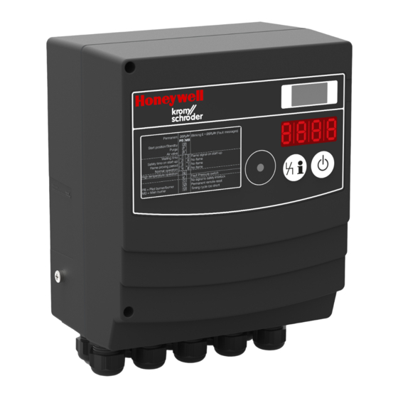
Burner control unit BCU 46x, 480
Cert. version 03.19
Contents
Contents
Burner control unit BCU 46x, 480. . . . . . . . . . 1
Contents . . . . . . . . . . . . . . . . . . . . . . . . . . . . . . 1
Safety. . . . . . . . . . . . . . . . . . . . . . . . . . . . . . . . . 1
Checking the usage . . . . . . . . . . . . . . . . . . . . .
parameter chip card . . . . . . . . . . . . . . . . . . . . 4
Cable selection and installation . . . . . . . . . . . 5
Wiring . . . . . . . . . . . . . . . . . . . . . . . . . . . . . . . . 5
Connection diagram . . . . . . . . . . . . . . . . . . . . 7
Flame control . . . . . . . . . . . . . . . . . . . . . . . . . . 12
Adjustment . . . . . . . . . . . . . . . . . . . . . . . . . . . 13
Commissioning. . . . . . . . . . . . . . . . . . . . . . . . 14
Manual mode . . . . . . . . . . . . . . . . . . . . . . . . . 15
Assistance in the event of malfunction . . . . 16
messages and parameters . . . . . . . . . . . . . . 5
Parameters and values . . . . . . . . . . . . . . . . . 5
Legend. . . . . . . . . . . . . . . . . . . . . . . . . . . . . . . 9
Technical data . . . . . . . . . . . . . . . . . . . . . . . . 9
Safety instructions . . . . . . . . . . . . . . . . . . . . . 30
Logistics . . . . . . . . . . . . . . . . . . . . . . . . . . . . . 31
Accessories . . . . . . . . . . . . . . . . . . . . . . . . . . 31
Certification . . . . . . . . . . . . . . . . . . . . . . . . . . 3
Contact . . . . . . . . . . . . . . . . . . . . . . . . . . . . . . 34
E
DK
S
N
P
GR
www.docuthek.com
Safety
Safety
Please read and keep in a safe place
Please read through these instructions
carefully before installing or operating. Following the
installation, pass the instructions on to the opera-
tor. This unit must be installed and commissioned
in accordance with the regulations and standards
in force. These instructions can also be found at
www.docuthek.com.
Explanation of symbols
• , 1 , , 3 ... = Action
▷
= Instruction
Liability
We will not be held liable for damage resulting from
non-observance of the instructions and non-com-
pliant use.
Safety instructions
Information that is relevant for safety is indicated in
the instructions as follows:
DANGER
Indicates potentially fatal situations.
WARNING
Indicates possible danger to life and limb.
CAUTION
Indicates possible material damage.
All interventions may only be carried out by qualified
gas technicians. Electrical interventions may only be
carried out by qualified electricians.
Conversion, spare parts
All technical changes are prohibited. Only use OEM
spare parts.
GB-1
Advertisement
Table of Contents

Subscribe to Our Youtube Channel
Related Manuals for Krom Schroder BCU 46 Series


Summary of Contents for Krom Schroder BCU 46 Series
-
Page 1: Table Of Contents
Safety Safety 035158 Please read and keep in a safe place www.docuthek.com Please read through these instructions Operating instructions carefully before installing or operating. Following the Burner control unit BCU 46x, 480 installation, pass the instructions on to the opera- tor. This unit must be installed and commissioned in accordance with the regulations and standards in force. -
Page 2: Checking The Usage
Type code Checking the usage Code Description Burner control units BCU 460, 465 and 480 are de- BCU 4 Series 4 burner control unit signed to control, ignite and monitor gas burners in Series 460 intermittent or continuous operation. They replace Series 465 the local control cabinet. - Page 3 Part designations Installation CAUTION Please observe the following to ensure that the BCU is not damaged: – The device must not be installed in a public place. It must be accessible to authorized personnel only. Unauthorized personnel could make changes which could cause the system to become unsafe or dangerous.
-
Page 4: Replacing The Power Module/Bus Module
Screwing on the BCU Replacing the power module/bus From inside: module/parameter chip card 1 Open the cover of the BCU. CAUTION Please observe the following to ensure that the BCU is not damaged: – Different power supply for the gas valves. -
Page 5: Cable Selection And Installation
Cable selection and installation Wiring ▷ Signal and control line for screw terminals max. CAUTION 2.5 mm (min. AWG 24, max. AWG 12), for spring Please observe the following to ensure that the force terminals max. 1.5 mm (min. AWG 24, BCU is not damaged: max. AWG 12). ▷ For the ionization and ignition cables, use un- –... - Page 6 ▷ Use plastic cable glands/conduit couplings with ▷ Screw terminals or spring force terminals are multiple cable grommet. These can be detached available for the BCU: with the plug-in connection terminals. Screw terminals, Order No. 74924876, ▷ Do not supply voltage to the outputs. spring force terminals, Order No.
-
Page 7: Connection Diagram
▷ The connection diagram shows BCU..E1 with Connection diagram LM..E1. ▷ Legend – see page 29 (Legend). BCU 460/LM..F0 GB-7... - Page 8 ▷ Legend – see page 29 (Legend). BCU 460/LM..F3 ▷ The connection diagram shows BCU..E1 with LM..E1. GB-8...
- Page 9 ▷ Legend – see page 29 (Legend). BCU 465/LM..F3 ▷ The connection diagram shows BCU..E1 with LM..E1. GB-9...
- Page 10 ▷ Legend – see page 29 (Legend). BCU 480/LM..F3 ▷ The connection diagram shows BCU..E1 with LM..E1. GB-10...
- Page 11 82 81 80 85 86 87 92 91 90 95 96 97 ▷ Set IC 40 to operating mode 11, see Actuator IC 40 connected to BCU/LM..F1 (staged control) IC 40 operating instructions or technical informa- F1 3,15 A ▷ Parameter I020 = 2. tion bulletin at www.docuthek.com.
-
Page 12: Flame Control
Flame control BCU 480 ▷ BCU 460, 465 = 1 flame amplifier Pilot burner = single-electrode operation/ ▷ BCU 480 = 2 flame amplifiers main burner = ionization: (BCU. ▷ In the case of UV control, use Elster UV sensors ▷... -
Page 13: Adjustment
Pilot burner = UVS/main burner = ionization: Pilot burner = UVC/main burner = UVS: ▷ Parameter A002 ≥ 5 µA. ▷ Parameter A002 ≥ 5 µA. ▷ Parameter I004 = 5. ▷ Parameter I004 = 8. 51 21 BM PE 51 21 BM PE 54 24 PE PE Pilot burner = UVC/main burner = UVC:... -
Page 14: Commissioning
3 Press the Reset/Information button on the BCU WARNING to confirm the new parameter settings. Risk of explosion! Check the system for tightness before commissioning. Do not start the BCU until the parameter settings and wiring are correct and the faultless processing of all input and output signals complies with the local standards. -
Page 15: Manual Mode
▷ After 3 seconds in this position, the μA value for ▷ The display indicates if the air ac- the flame signal XX.X is displayed instead of the tuator has been opened. The pilot burner is in program status. operation. ▷... -
Page 16: Assistance In The Event Of Malfunction
Assistance in the event of WARNING malfunction Risk of explosion! The pre-purge time is not includ- ed in the program. Maintain state P.0. until the com- DANGER bustion chamber has been adequately ventilated. To avoid harm to persons and damage to the unit, 3 Press the Reset/Information button for 1 s. - Page 17 ! Terminal boot not properly connected to flame rod. Gas/air ratio incorrect. Flame not contacting burner ground as the result ? Start-up – no ignition spark – the display of excessively high gas or air pressure. blinks and indicates E 02 E A2 Burner or BCU not (adequately) grounded.
- Page 18 • Check input 41. Short-circuit or discontinuity on the flame signal ▷ Input 41 may only be activated if the valve is cable. open. Soiled UV sensor. • Check input 40. • Remedy fault. ▷ Input 40 may only be activated if the valve is in the position for ignition capacity.
- Page 19 • Check parameter A056 (Measurement time V and change using BCSoft. • If the fault cannot be remedied by doing this, remove the unit and return it to the manufacturer ? The display blinks and indicates E 34 for inspection. ! Faulty actuation of the air valve. ! Voltage is applied to the air valve outputs (65 – 67).
- Page 20 ? The display blinks and indicates ! The time between two starts is less than the min. time (timing cycle). • Comply with max. number of start-ups (n) per ? The display indicates E 89 E 94 E 95 E 96 minute: E 97 E 98 E 99...
- Page 21 • Check the wiring and ensure that the device and • If the fault cannot be remedied by doing this, the inputs are supplied with the same phase. remove the unit and return it to the manufacturer for inspection. ? The display blinks and indicates E 97 ! No PCC.
- Page 22 • Create a SafetyLink project with BCSoft and transfer the configuration to the device. ? The display blinks and indicates ! No input signal for the valve proof of closure switch (POC) during standby. • Check the wiring. ? The display blinks and indicates ▷...
- Page 23 • Check the electrical wiring of the air pressure ! Poor shielding. switch. • Check whether the shield is connected to the • Check voltage supply to terminal 37. shield clips in the PROFIBUS DP plugs in full and • Check the air pressure switch setpoint. over a wide area.
- Page 24 • Assign a network name corresponding to the Replacing the fuse ▷ The device fuses F1, F2 and F3 can be removed default network name (bcu-460-xxx) or use the default name as a suffix of an individually as- for inspection. ▷...
-
Page 25: Reading Off The Flame Signal, Fault Messages And Parameters
Reading off the flame signal, fault Parameters and values messages and parameters Application parameters ▷ If the unit is switched on, information about the Parameter name Param- flame signal intensity, the last 10 event messages eter No. Parameter value (e.g. Power ON, error E002) and the parameter Switch-off threshold 1 A001 values can be read off by repeatedly pressing... - Page 26 Parameter name Parameter name Param- Param- eter No. eter No. Parameter value Parameter value Over-run Air actuator (bus) 0 = Off 0 = Off 1 = MAX to MIN A043 1 = Post-ventilation A075 2 = MAX to LOW FIRE 2 = Low fire;...
- Page 27 Parameter name Parameter name Param- Param- eter No. eter No. Parameter value Parameter value Purge (bus) Function of sensor 1 0 = Off 0 = No function 1 = Via FS bus 1 = APS Purge A087 2 = Via terminal 2 = APS Stage 1 3 = Via NFS bus 3 = APS Purge &...
- Page 28 Interface parameters Parameter name Param- ▷ Interface parameters I040 to I099 are set at the eter No. Parameter value Function of input 1 factory and normally do not need to be adjusted. 0 = Off CAUTION 1 = Sensor 1 2 = Sensor 2 Changing the default settings of the interface pa- 3 = Sensor 3...
-
Page 29: Legend
Legend Technical data Ambient conditions Ready for operation Avoid direct sunlight or radiation from red-hot Safety interlocks (limits) surfaces on the unit. Avoid corrosive influences, e.g. salty ambient air High temperature operation or SO The unit may only be stored/installed in enclosed Gas valve rooms/buildings that are not accessible to the public. -
Page 30: Safety Instructions
Total current for the simultaneous activation of the Safety instructions valve outputs (terminals 60, 61, 62, 63 and 64) Scope of application: as set out in “Industrial and of the ignition transformer (terminal 51), pro- thermoprocessing equipment – Part 2: Safety re- tected by F1/F2: max. 2.5 A. quirements for combustion and fuel handling sys- Total current for the simultaneous activation of the tems”... -
Page 31: Logistics
Fastening set Logistics ▷ To ensure a gap between the BCU and the Transport mounting surface with higher temperatures. Protect the unit from external forces (blows, shocks, vibration). Transport temperature: see page 29 (Technical data). Transport is subject to the ambient conditions de- scribed. -
Page 32: Certification
SIL, PL Certification Declaration of conformity For systems up to SIL 3 pursuant to EN 61508. Pursuant to EN ISO 13849-1, Table 4, the BCU can We, the manufacturer, hereby declare that the prod- be used up to PL e. ucts BCU 460, BCU 465 and BCU 480 comply with Safety-specific characteristic values the requirements of the listed Directives and Standards. - Page 33 FM approved Factory Mutual (FM) Research Class: 7610 “Combustion Safeguards and Flame Sensing Systems” Suitable for applications pursuant to NFPA 86. Directive on the restriction of the use of hazardous substances (RoHS) in China Scan of the Disclosure Table China RoHS2 – see certificates at www.docuthek.com GB-33...
-
Page 34: Contact
Contact Contact If you have any technical questions, please contact your local branch office/agent. The addresses are Elster GmbH available on the Internet or from Elster GmbH. Strotheweg 1, D-49504 Lotte (Büren) Tel. +49 541 1214-0 We reserve the right to make technical modifications Fax +49 541 1214-370 in the interests of progress.
Need help?
Do you have a question about the BCU 46 Series and is the answer not in the manual?
Questions and answers