Table of Contents
Advertisement
050
D
GB
F
NL
I
TR
CZ
PL
RUS
H
Operating instructions
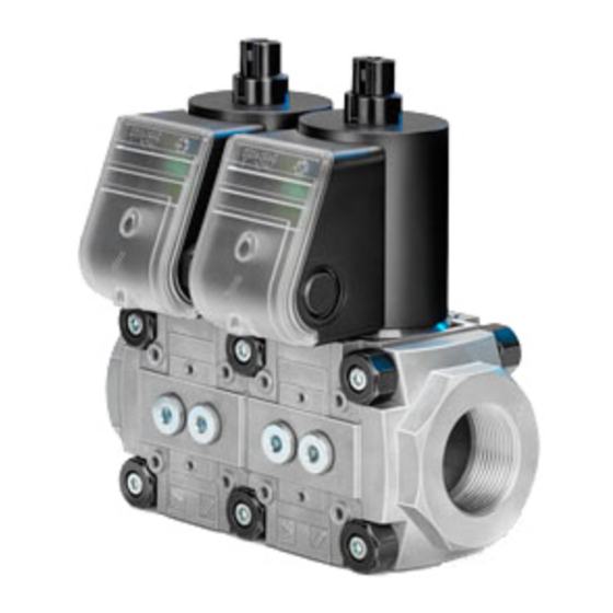
Solenoid valve for gas VAS 1 - ,
double solenoid valve VCS 1 -
Cert. version 07.19
Contents
Contents
Contents . . . . . . . . . . . . . . . . . . . . . . . . . . . . . . 1
Safety. . . . . . . . . . . . . . . . . . . . . . . . . . . . . . . . . 1
Checking the usage . . . . . . . . . . . . . . . . . . . . .
Tightness test . . . . . . . . . . . . . . . . . . . . . . . . . . 6
Commissioning. . . . . . . . . . . . . . . . . . . . . . . . . 6
Replacing the actuator . . . . . . . . . . . . . . . . . . 6
Replacing the damping unit . . . . . . . . . . . . . . 8
Maintenance . . . . . . . . . . . . . . . . . . . . . . . . . . . 8
Accessories . . . . . . . . . . . . . . . . . . . . . . . . . . . 9
Pressure switch for gas DG..VC. . . . . . . . . . . . . 9
Bypass/pilot gas valves . . . . . . . . . . . . . . . . . . . 9
Tightness control TC 1V . . . . . . . . . . . . . . . . . . 11
Attachment block. . . . . . . . . . . . . . . . . . . . . . . 12
Seal set for sizes 1 - 3 . . . . . . . . . . . . . . . . . . . 13
element . . . . . . . . . . . . . . . . . . . . . . . . . . . . . . 13
Technical data . . . . . . . . . . . . . . . . . . . . . . . . 1
Air flow rate Q. . . . . . . . . . . . . . . . . . . . . . . . . 14
Safety information in accordance with
EN 61508- . . . . . . . . . . . . . . . . . . . . . . . . . . . 14
Designed lifetime . . . . . . . . . . . . . . . . . . . . . . 15
Logistics . . . . . . . . . . . . . . . . . . . . . . . . . . . . . 15
Certification . . . . . . . . . . . . . . . . . . . . . . . . . . 15
Contact . . . . . . . . . . . . . . . . . . . . . . . . . . . . . . 16
E
DK
S
N
P
GR
www.docuthek.com
Safety
Safety
Please read and keep in a safe place
Please read through these instructions
carefully before installing or operating. Following the
installation, pass the instructions on to the opera-
tor. This unit must be installed and commissioned
in accordance with the regulations and standards
in force. These instructions can also be found at
www.docuthek.com.
Explanation of symbols
• , 1 , , ... = Action
▷
= Instruction
Liability
We will not be held liable for damage resulting from
non-observance of the instructions and non-com-
pliant use.
Safety instructions
Information that is relevant for safety is indicated in
the instructions as follows:
DANGER
Indicates potentially fatal situations.
WARNING
Indicates possible danger to life and limb.
CAUTION
Indicates possible material damage.
All interventions may only be carried out by qualified
gas technicians. Electrical interventions may only be
carried out by qualified electricians.
Conversion, spare parts
All technical changes are prohibited. Only use OEM
spare parts.
Changes to edition 10.17
The following chapters have been changed:
-
Installation
-
Accessories
-
Technical data
-
Safety instructions
-
Logistics
-
Certification
GB-1
Advertisement
Table of Contents

Related Manuals for Krom Schroder VAS Series


Summary of Contents for Krom Schroder VAS Series
-
Page 1: Table Of Contents
Safety Safety 050 Please read and keep in a safe place www.docuthek.com Please read through these instructions Operating instructions carefully before installing or operating. Following the Solenoid valve for gas VAS 1 – , installation, pass the instructions on to the opera- double solenoid valve VCS 1 – ... -
Page 2: Checking The Usage
Mains voltage, electrical power consumption, ambi- Checking the usage ent temperature, enclosure, inlet pressure and instal- Intended use lation position: see type label. Gas solenoid valves VAS for safeguarding gas or air Elster GmbH on various appliances. Double solenoid valves VCS Osnabrück, Made in Germany are combinations of two gas solenoid valves VAS. - Page 3 ▷ Installation position: black solenoid actuator in Retaining frame ▷ If two controls (regulators or valves) are as- the vertical upright position or tilted up to the horizontal, not upside down. sembled, a retaining frame with double block seal must be fitted, see accessories, seal set for sizes 1 –...
- Page 4 Wiring WARNING Attention! Please observe the following to ensure that no damage occurs: – Electric shocks can be fatal! Before working on possible live components, ensure the unit LV1 N is disconnected from the power supply. – The solenoid actuator heats up during opera- tion.
- Page 5 Socket 1 = N (–), 2 = LV1 (+), 3 = LV1 N (-) = blue N (-) = blue (-) 1 LV1 (+) = black (-) 1 LV1 (+) = black (-) 1 (+) = black, N (–) = blue schwarz black black...
-
Page 6: Tightness Test
Setting the start gas rate on VAS../L, VCS..L Tightness test ▷ The start gas rate can be set by turning the 1 Close the gas solenoid valve. damping unit a maximum of 5 turns. To be able to check the tightness, shut off the ▷... - Page 7 VAS without damping VAS 1–3 1 Disconnect the system from the electrical power supply. Shut off the gas supply. ▷ Remove the M20 cable gland or other type of connection. Slide seal under the second groove. 1 Position new actuator. 1...
-
Page 8: Replacing The Damping Unit
Gewindestifte M3 fest 16 Set the start gas rate, see page 6 (Setting einschrauben. Maintenance the start gas rate on VAS../L, VCS..L). The con- nection between solenoid actuator and damping CAUTION unit must then be checked for tightness. In order to ensure smooth operation, check the tightness and function of the VAS: –... -
Page 9: Accessories
Accessories Pressure switch for gas DG..VC ▷ The pressure switch for gas monitors the inlet pressure p , the outlet pressure p and the in- terspace pressure p VBY for VAS 1 Medium and ambient temperatures: 0 to +60°C (32 to 140°F), no condensation permitted. Enclosure: IP 54. - Page 10 Setting the flow rate ▷ The flow rate can be set by turning the flow rate restrictor (4 mm hexagon socket) ¼ of a turn. 10 Remove the sealing plugs on the mounting side of the bypass valve. VAS 1 to VAS 1 11 Remove the nuts from the connection parts on the mounting side of the main valve.
-
Page 11: Checking The Bypass/Pilot Gas Valve For Tightness
16 Check for tightness, see accessories, checking Tightness control TC 1V the bypass/pilot gas valve for tightness. 1 Disconnect the system from the electrical power supply. Checking the bypass/pilot gas valve for Shut off the gas supply. tightness ▷ The solenoid actuator cannot be rotated on so- 1 To be able to check the tightness, shut off the lenoid valves with proof of closure switch VCx..S downstream pipeline as close as possible to the... -
Page 12: Cable Gland Set For Double Solenoid Valves
9 After completing the wiring, tightness test and commissioning for the TC, refit the housing cover on the TC. Cable gland set for double solenoid valves ▷ When wiring a double solenoid valve, the connection boxes are to be connected using a cable gland set. VCx 1 VCx 2 Connect... -
Page 13: Seal Set For Sizes 1 - 3
Seal set for sizes 1 – Technical data ▷ When retrofitting accessories or a second valVario Ambient conditions control or when servicing, we recommend Icing, condensation and dew in and on the unit are replacing the seals. not permitted. Avoid direct sunlight or radiation from red-hot surfaces on the unit. -
Page 14: Air Flow Rate Q
Valve housing: aluminium, Air flow rate Q valve seal: NBR. Air flow rate Q for a pressure loss of ∆p = 1 mbar Connection flanges: (0.4 "WC) VAS/VCS 1 – 3 with internal thread: Rp pursuant to ISO 7-1, NPT pursuant to ANSI/ ∆p 1 mbar (0,4 "WC) ASME;... -
Page 15: Designed Lifetime
Designed lifetime Certification This information on the designed lifetime is based on Declaration of conformity using the product in accordance with these operating instructions. Once the designed lifetime has been reached, safety-relevant products must be replaced. Designed lifetime (based on date of manufacture) in We, the manufacturer, hereby declare that the prod- accordance with EN 13611, EN 161 for VAS: ucts VAS with product ID No. -
Page 16: Contact
FM approved* Factory Mutual (FM) Research Class: 7400 and 7411 Safety overpressure slam shut valves. Designed for applications pursuant to NFPA 85 and NFPA 86. ANSI/CSA approved* Canadian Standards Association – ANSI Z21.21 and CSA 6.5 UL listed* Underwriters Laboratories – UL 429 “Electrically operated valves”.
Need help?
Do you have a question about the VAS Series and is the answer not in the manual?
Questions and answers