Table of Contents
Advertisement
Quick Links
Burner control units BCU 560, BCU 565
Technical Information · GB
6 Edition 02.16
• For monitoring and controlling modulating or staged burners for multiple
burner applications with a central air supply
• For directly ignited burners of unlimited capacity in intermittent or
continuous operation
• Optionally with valve proving system
• Optionally with menox
thermal NO
x
• Flexible range of applications due to parameterization possibilities
• PROFINET fieldbus connection using optional bus module
• Assume safety functions pursuant to EN 746-2
• EU certified
• Certified for systems up to SIL 3 and PL e
®
operating mode to reduce the formation of
Advertisement
Table of Contents

Subscribe to Our Youtube Channel
Related Manuals for Krom Schroder BCU 560


Summary of Contents for Krom Schroder BCU 560
-
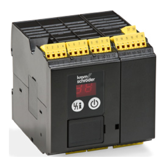
Page 1: Burner Control Units Bcu 560, Bcu 565
Burner control units BCU 560, BCU 565 Technical Information · GB 6 Edition 02.16 • For monitoring and controlling modulating or staged burners for multiple burner applications with a central air supply • For directly ignited burners of unlimited capacity in intermittent or continuous operation • Optionally with valve proving system... -
Page 2: Table Of Contents
Contents Burner control units BCU 560, BCU 565 . . . . . . . . . . . . . . . 1 6.1 Tightness control ......31 6.1.1 Test instant. - Page 3 13.1 Installation........106 BCU 560, BCU 565 · Edition 02.16...
- Page 4 Contact . . . . . . . . . . . . . . . . . . . . . . . . . . . . . . . . . . . . . . . 130 BCU 560, BCU 565 · Edition 02.16...
-
Page 5: Application
BCU to transfer the parameters, for example when Burner control units BCU 560 or BCU 565 control, ignite and replacing the unit. monitor gas burners in intermittent or continuous operation. - Page 6 DIN rail installation. It is pushed on to the BCU from the side. Thanks to the operator-control unit OCU, display functions and operation of the BCU can be relocated to the control cabinet door. BCU 560, BCU 565 · Edition 02.16...
-
Page 7: Examples Of Application
The gas/air mixture is adjusted to the requirements of the applications using the parameters of pre-ventilation and post- ventilation. The pressure switch monitors the air flow in the air supply line or in the flue gas exhaust. BCU 560, BCU 565 · Edition 02.16... -
Page 8: Two-Stage-Controlled Burner
Depending on the parameter set- ting, the air valve is actuated to open Process control (PCC) and close by the program or externally via the input at terminal 2. FCU 500 TZI/TGI ϑ BCU 560..C0F3 µC VR..L BCU 560, BCU 565 · Edition 02.16... -
Page 9: Modulating-Controlled Burner
Process control (PCC) FCU 500 ϑ BCU 560..C0F1 µC TZI/TGI 53 54 55 BCU 560, BCU 565 · Edition 02.16... -
Page 10: Flame Control Using The Temperature
HT output that the furnace system is in High tempera- ture mode (HT). When the HT input is activated, the burner control units switch to High temperature mode. They operate without evaluating the flame signal and their internal flame control is non-functional. BCU 560, BCU 565 · Edition 02.16... -
Page 11: Mode To Reduce No X Formation
IC 40 and butterfly valve BVH. An air pressure switch upstream of the burner monitors the functioning of the butterfly valve. In addition, air/gas ratio monitoring for the zone or the furnace is required. BCU 560, BCU 565 · Edition 02.16... -
Page 12: Profinet Connection Using Bus Module Bcm
Control signals that are relevant for safety, such as the safety interlocks, purge and HT input, are transferred independently of the bus communication by separate cables. BCU 560, BCU 565 · Edition 02.16... -
Page 13: On/Off Rotary Impulse Control For Burners Up To 360 Kw
BCU 560. The centrally checked safety functions such as pre-purge, tightness test, flow detector and pressure switch check (gas , gas , air ) are provided min. max. min. by the FCU 500. BCU 560, BCU 565 · Edition 02.16... -
Page 14: Modulating Burner Control
90° 0° 47 48 control system, tightness test, flow detec- Purge tor and pressure switch check (gas min. , air ) are provided by the max. min. FCU 500. BCU 560, BCU 565 · Edition 02.16... -
Page 15: Certification
Factory Mutual Research Class: 7400 Process Control Valves. Designed for applications pursuant to NFPA 85 and NFPA 86. www.approvalguide.com Eurasian Customs Union The products BCU 560 and BCU 565 meet the technical speci- fications of the Eurasian Customs Union. BCU 560, BCU 565 · Edition 02.16... -
Page 16: Function
3 .1 .1 BCU 560 . .F3 with ionization control in double- electrode operation Alternative flame control, see page 22 (Flame control). ϑ 62 61 11 12 max. 1 A; 24 V DC, 250 V AC 3,15AT µC BCU 560..F3 0,6 × I +24 V BCU 560, BCU 565 · Edition 02.16... -
Page 17: Bcu 560
Explanation of symbols, see page 126 (Legend) ϑ 62 61 11 12 max. 1 A; 24 V DC, 250 V AC 3,15AT µC BCU 560..F1 0,6 × I +24 V (P40 = 2/3) => 51 BCU 560, BCU 565 · Edition 02.16... -
Page 18: Bcu 560
Explanation of symbols, see page 126 (Legend) ϑ 62 61 11 12 max. 1 A; 24 V DC, 250 V AC 3,15AT (P69 = 13) AUTO µC BCU 560..F2 0,6 × I +24 V BCU 560, BCU 565 · Edition 02.16... -
Page 19: Bcu 565
Electrical connection, see page 106 (Project planning infor- mation) Explanation of symbols, see page 126 (Legend) ϑ 62 61 11 12 max. 1 A; 24 V DC, 250 V AC 3,15AT µC BCU 565..F3 0.6 × I +24 V BCU 560, BCU 565 · Edition 02.16... -
Page 20: Bcu 565
Explanation of symbols, see page 126 (Legend) ϑ 62 61 11 12 max. 1 A; 24 V DC, 250 V AC 3,15AT µC BCU 565..F1 0.6 × I +24 V (P40 = 2/3) => 51 BCU 560, BCU 565 · Edition 02.16... -
Page 21: Bcu 565
Explanation of symbols, see page 126 (Legend) ϑ 62 61 11 12 max. 1 A; 24 V DC, 250 V AC 3,15AT (P69 = 13) AUTO µC BCU 565..F2 0.6 × I +24 V BCU 560, BCU 565 · Edition 02.16... -
Page 22: Flame Control
µC max. 1 A; BCU 560..F1 24 V DC, 0.6 × I 250 V AC BCU 560..F1 +24 V (P40 = 2/3) => 51 3,15AT (P40 = 2/3) => 51 µC BCU 560, BCU 565 · Edition 02.16 BCU 560..F1... -
Page 23: Bcu 560 Program Sequence
(P42) starts to elapse ▼ Safety time 1 t (P94) running, ignition in process, valves for 1 gas stage open. ▼ If no flame detected: max. 3 start-up attempts (P07) or fault lock-out ▼ BCU 560, BCU 565 · Edition 02.16... -
Page 24: Bcu 565 Program Sequence
Post-ventilation time t running (P39) air actuator opens ▼ Air actuator is closed, Safety time 1 t running (P94), running time starts to elapse (P42) ignition in process, valves for 1 gas stage open. ▼ BCU 560, BCU 565 · Edition 02.16... -
Page 25: Air Control
The capacity is controlled during operation by an external temperature control system. BCU 5xx..F3 BCU 5xx..F3 ϑ VR..L µC µC BCU 5xx..F3 BCU 5xx..F3 >750° >750° FCU 500..F0 FCU 500 47 48 Purge Purge VR..L BCU 560, BCU 565 · Edition 02.16... -
Page 26: Capacity Control
As soon as there is a purge signal at terminal 50 of BCU..F1/ F2, the control element is activated by the outputs for capacity control to approach the position for pre-purge. The protective BCU 560, BCU 565 · Edition 02.16... -
Page 27: Bcu
1. The gas valves for the 1 stage are opened and the burner is ignited (on the BCU..C1 after a successful valve check). After the operating BCU 560, BCU 565 · Edition 02.16... -
Page 28: Menox ® Low No X Mode
(TSC..B). ▼ BIC..M BCU 565..D2 TZI/ IC 40 + BVH A burner BIC..M in conjunction with a burner control unit BCU..D2 is required for safe burner operation in menox ® mode. BCU 560, BCU 565 · Edition 02.16... - Page 29 No ignition takes place in the burner tube. The combustion process is relocated to the combustion chamber. The oxidation reactions take place without a visible flame. Compared to traditional flame mode, the reaction zone is BCU 560, BCU 565 · Edition 02.16...
-
Page 30: Bcu
Hot air compensation and ratio control are not the respon- sibility of the BCU. These functions must satisfy the require- ments of a protective system pursuant to EN 746-2 and be implemented externally. BCU 560, BCU 565 · Edition 02.16... -
Page 31: Valve Proving System
1200 kW (NFPA 86: from 117 kW or 400,000 Btu/h). The tightness control function satisfies the requirements of EN 1643 (Valve proving systems for automatic shut-off valves for gas burners and gas appliances). BCU 560, BCU 565 · Edition 02.16... -
Page 32: Test Instant
This ensures that the µC test volume V can be vented during the tightness test with the air/gas ratio control closed. 47 48 Purge IC 20 + BVA BCU 560, BCU 565 · Edition 02.16... -
Page 33: Program Sequence
V2 is around atmospheric pressure and the volume downstream of V2 is at least 5 × higher than the volume t M = P56 t M = P56 between the valves. – ▼ p Z > p Z > – BCU 560, BCU 565 · Edition 02.16... - Page 34 Z > p Z > between the valves. – t L = P59 t L = P59 t M = P56 t M = P56 – p Z > p Z > – BCU 560, BCU 565 · Edition 02.16...
-
Page 35: Test Period T P
. The longer the measurement time t , the greater the sensitivity of the tightness control. The measurement time ▼ is set using parameter 56 to a value between 3 and 3600 s, see page 97 (Measurement time V BCU 560, BCU 565 · Edition 02.16... - Page 36 VG 15 0.07 VG 20 0.12 12.3 VG 25 17.7 VG 40/VK 40 31.4 VG 50/VK 50 VG 65/VK 65 VG 80/VK 80 VK 100 VK 125 13.6 VK 150 VK 200 VK 250 BCU 560, BCU 565 · Edition 02.16...
- Page 37 /h x 1000 l/h Leakage BCU 570..C1 = 200 l/h rate Q 1000 x 1 m Test volume V = 1.1 l + 9.5 m x 3.3 l/m = 32.45 l see page 36 (Test volume V BCU 560, BCU 565 · Edition 02.16...
-
Page 38: Proof Of Closure Function
POC switch. If a signal is still re- ceived at terminal 45 from the POC switch after a timeout time of 10 s, the BCU performs a fault lock-out with fault message c8. BCU 560, BCU 565 · Edition 02.16... -
Page 39: Bcsoft
In addition to the engineering tool BCSoft, an opto-adapter or Bluetooth adapter is required to read the device parameters in and out, see also page 113 (BCSoft). BCU 560, BCU 565 · Edition 02.16... -
Page 40: Profinet
IO devices start up or sending a diag- nostic message from the IO device to the IO controller during operation. The data read or written acyclically by read/write BCU 560, BCU 565 · Edition 02.16... -
Page 41: Bcu And Bus Module Bcm
Profinet use. For information on planning and the structure of a Profibus network and the components to be used (e.g. cables, lines and switches), see Profinet Installation Guide at www.profibus.com. BCU 560, BCU 565 · Edition 02.16... -
Page 42: Gsd File For Plc Configuration
The steps required to integrate the file are described in the instructions for the engineering tool for your automation system. For parameter settings on the BCU and code switch settings on the BCM, see page 104 (Fieldbus communication). BCU 560, BCU 565 · Edition 02.16... -
Page 43: Modules For Cyclic Data Exchange
BCM 500. All modules required for cyclic data exchange between the controller and the burner control units BCU 560 and BCU 565 are shown in the following table. The modules are assigned to the slots. - Page 44 The digital input and output signals from the burner control The output byte describes the digital signals which are output units BCU 560, BCU 565 and BCU 580 are included in this by the PLC (IO controller) to the BCU (IO device). The digital sig- module.
- Page 45 Data type Format Value 0 – 255 (see 0 – 255 code table “BCU56x_ Warning signals Byte (see GSD_Codetabelle. code table “BCU56x_ Status signals Byte xlsx” at GSD_Codetabelle. www.docuthek.com) xlsx” at www.docuthek.com) ▼ BCU 560, BCU 565 · Edition 02.16...
- Page 46 Bit Byte n Byte n+1 Data type Format Value Remaining times 0 – 6554 of the valve prov- Word (0 – 6554 s) ing system ▼ BCU 560, BCU 565 · Edition 02.16...
- Page 47 3 Free Terminal 51 Free BOOL 4 Terminal 44 Terminal 52 Free BOOL 5 Terminal 45 Terminal 65 Free BOOL 6 Terminal 46 Terminal 66 Free BOOL 7 Terminal 47 Terminal 67 Free BOOL BCU 560, BCU 565 · Edition 02.16...
-
Page 48: Indexes For Acyclic Communication
Operator statistics, counter 1005 Operator statistics, faults/warnings 1006 Fault history 1007 Power module statistics The contents and description of the indexes are described in the code table “GSD Codes BCU 56x” (download from www.docuthek.com). BCU 560, BCU 565 · Edition 02.16... -
Page 49: Program Step/Status
Over-run up to minimum capacity Post-purge Remote control with OCU Data transfer (programming mode) – – Device Off In Manual mode, two dots blink on the display. Air actuator (control element/valve) is open. BCU 560, BCU 565 · Edition 02.16... -
Page 50: Fault Signalling
Parameter set contains illegal settings Air valve control defective Incompatible bus module Power module defective Relay contact error Fuse defective Device fuse F1 is defective Inlet valve(s) leaking Leak found on inlet valve ▼ BCU 560, BCU 565 · Edition 02.16... - Page 51 255 s Position for ignition capacity has not been reached Ignition capacity not reached after 255 s Communication with bus module Bus module fault Parameter chip card (PCC) Incorrect or defective PCC ▼ BCU 560, BCU 565 · Edition 02.16...
- Page 52 Flame failure during flame proving period 1 dur- Flame failure during flame proving period 1 ing multi-flame control Flame failure during burner 1 operation during Flame failure during burner 1 operation multi-flame control BCU 560, BCU 565 · Edition 02.16...
-
Page 53: Parameters
Time in seconds Pre-purge time tPV 0 – 6000 Time in seconds 6000 Air flow monitoring during pre- With safety shut-down purge With fault lock-out Pre-ventilation time tVL 0 – 250 Time in seconds ▼ BCU 560, BCU 565 · Edition 02.16... - Page 54 41 = 1, 2 or 3 Up to minimum capacity Low fire over-run 10 s 20 s 30 s 40 s Controller enable signal delay time tRF 0 – 250 Time in seconds ▼ BCU 560, BCU 565 · Edition 02.16...
- Page 55 Time in seconds Switchover to menox ® operating On next burner start mode Immediately Unlimited Operating time in Manual mode 5 minutes Purge with Low signal Function of terminal 50 Purge with High signal ▼ BCU 560, BCU 565 · Edition 02.16...
- Page 56 Multi-flame control (MFC) start-up condi- tions AND with emergency stop (trm. 46) AND with air (trm. 47) min. Function of terminal 68 AND with air flow monitoring (trm. 48) Multi-flame control (MFC) operating condi- tions ▼ BCU 560, BCU 565 · Edition 02.16...
- Page 57 1/0 in menox mode with 2 gas paths Fieldbus communication With address check No address check Safety time 1 tSA1 2, 3, 5, 10 Time in seconds Flame proving period 1 tFS1 0 – 20 Time in seconds BCU 560, BCU 565 · Edition 02.16...
-
Page 58: Scanning The Parameters
BCU performs a safety shut-down with subsequent fault lock- out or up to two further start-up attempts. The number of start-up attempts can be defined using parameter 07, see page 62 (Burner 1 start-up attempts). BCU 560, BCU 565 · Edition 02.16... -
Page 59: Flame Control
Parameter 04 = 2: flame control is performed with a UV sensor for continuous operation (UVD). The reaction times of the BCU and UV sensor for continuous operation are coordinated so that the set safety time during operation (parameter 19) is not extended. BCU 560, BCU 565 · Edition 02.16... -
Page 60: High Temperature Operation
▼ When the HT input is activated (terminal 49), the burner control unit reverts to High temperature mode, i.e.: the BCU operates BCU 560, BCU 565 · Edition 02.16... - Page 61 If no flame signal is present when High temperature mode is tion check (recommended in the case of UV control with UVS). deactivated, the burner control unit performs a fault lock-out, regardless of parameter 06. Parameter 06 = 3 (BCU..D1) ϑ ϑ BCU 560, BCU 565 · Edition 02.16...
-
Page 62: Behaviour During Start-Up
BCU safety shut-down with subsequent fault lock-out. The fault message 04 will flash in the BCU display depending on the burner operating mode. BCU 560, BCU 565 · Edition 02.16... -
Page 63: Burner Application
(P95) is set to a value ≥ 2 s. the burner in order to release the gas supply to the burner. 14 15 BCU 570 14 15 µC BCU 570 µC 47 48 17-18 47 48 17-18 ▼ BCU 560, BCU 565 · Edition 02.16... - Page 64 Valves V1 and V3 open to start the burner. The burner is started with a limited ignition capacity using gas valve V3. After the flame proving period t has elapsed, valve V2 opens to en- able the 2 gas stage. ▼ BCU 560, BCU 565 · Edition 02.16...
- Page 65 (as when P78 = 0) with the pre-ventilation time defined in parameter 36. The air control valve is in the ”high” position Process Control (PCC) for flame mode. ϑ BCU 565..F1 µC ▼ IC 40 + BVH BCU 560, BCU 565 · Edition 02.16...
- Page 66 BCU. The air pressure switch and the position of the IC are checked by terminals 48, 51 and 52 of the BCU. The BCU signals a fault if the desired state is not reached within the time set in parameter 42. BCU 560, BCU 565 · Edition 02.16...
- Page 67 V2 opens to enable the 2 stage and the air control valve is moved to the ”high” position. ϑ 14 15 BCU 565..F1 µC IC 40 + BVHS ▼ BCU 560, BCU 565 · Edition 02.16...
- Page 68 53 and 55 of the BCU. The positions are checked by terminals 51 and 52 of the BCU. The BCU signals a fault if the relevant position is not reached within the time set in parameter 42. BCU 560, BCU 565 · Edition 02.16...
- Page 69 36. The and in menox ® mode. air control valve is set to the "high" position for this purpose. Process Control (PCC) ϑ BCU 565..F1 µC ▼ IC 40 + BVH BCU 560, BCU 565 · Edition 02.16...
- Page 70 BCU. The air pressure switch and the position of the IC are checked by terminals 48, 51 and 52 of the BCU. The BCU signals a fault if the desired state is not reached within the time set in parameter 42. BCU 560, BCU 565 · Edition 02.16...
-
Page 71: Sa1
If the ϑ signal (terminal 1) drops out during safety time 1, the valves will not be switched off until the end of safety time 1. BCU 560, BCU 565 · Edition 02.16... -
Page 72: Behaviour During Operation
Taking into account national standards and requirements, A safety shut-down with subsequent fault lock-out takes place it must be clarified whether the option may be used. in the event of flame failure during operation. BCU 560, BCU 565 · Edition 02.16... -
Page 73: Minimum Operating Time T
(standby) and the burner is not ignited. The minimum operating time can be cancelled by switching off the BCU or if a safety shut-down occurs. BCU 560, BCU 565 · Edition 02.16... -
Page 74: Safety Limits
42 or until the position for maximum capacity is confirmed input (terminal 47). by the actuator. min. BCU 560, BCU 565 · Edition 02.16... -
Page 75: Safety Time During Operation
1 s. In accordance with EN 746-2, the safety time of the installation during operation (total closing time) may not exceed 3 s. The requirements of national standards and regulations must be satisfied. BCU 560, BCU 565 · Edition 02.16... -
Page 76: Air Control
(terminal 48), a safety shut-down with subsequent fault lock-out will be performed. Air flow monitoring is to be set on the basis of the relevant ap- plication standard (e.g. EN 676, EN 746-2, NFPA 85 or NFPA 86). BCU 560, BCU 565 · Edition 02.16... -
Page 77: Pre-Ventilation Time T
Parameter setting for this example sequence: P23 = 0; P48 = 1; P36 > 0, see also page 74 (Air pressure cut-out delay). The gas valve does not open until the pressure switch has switched. BCU 560, BCU 565 · Edition 02.16... -
Page 78: Capacity Control
If the position is not reached within the timeout time of 255 s, the BCU will display fault message A , A or A (maximum, ignition or minimum capacity not reached), see page 50 (Fault signalling). ▼ BCU 560, BCU 565 · Edition 02.16... - Page 79 BCU and the 3-point step controller can be adjusted so ▼ that the control range of the actuator is between the positions for maximum and ignition capacity. µC BCU 560..F1 12 11 3 2 1 BCU 560, BCU 565 · Edition 02.16...
- Page 80 (A , A or A ) will be displayed, see page 50 (Fault signalling). In addition, the actuator will be moved to the set position for minimum capacity using the output at terminal 54. BCU 560, BCU 565 · Edition 02.16...
- Page 81 Terminal 52 rate checks the position for ignition capacity. If the position is not Purge Maximum capacity reached within the timeout time of 255 s, a safety shut-down ▼ BCU 560, BCU 565 · Edition 02.16...
- Page 82 [s] ▼ IC 40 (operating mode 27) Signal at terminal Position Butterfly valve position Closed Closed Ignition Minimum/Ignition capacity Any position between mini- 0 – 20 mA mum and maximum capacity Purge Maximum capacity BCU 560, BCU 565 · Edition 02.16...
- Page 83 The actuator can be moved to the positions for maximum capacity or ignition capacity by the user. 3-point step operation is not possible. No timeout is + F - active when approaching these positions. ▼ 0° 90° BCU 560, BCU 565 · Edition 02.16...
- Page 84 (Running time). Parameter 41 (Running time selection) must be set to 1 to adjust this behaviour. BCU 560, BCU 565 · Edition 02.16...
-
Page 85: Running Time Selection
(Running time). After this time has elapsed, the BCU will initiate the next program step. Approaching the position for maximum capacity is signalled and monitored. BCU 560, BCU 565 · Edition 02.16... -
Page 86: Low Fire Over-Run
(terminals 17, 18) is closed and the controller enable time in seconds. During this time, the gas valve remains open. output (terminal 56) activated. The display changes to 04. The air valve is closed with deactivated start-up signal (ϑ). BCU 560, BCU 565 · Edition 02.16... -
Page 87: Air Actuator Control
The air actuator can be activated externally via the input at ter- minal 2 for cooling the burner in the start-up position (standby). This function is not available during burner start-up and during operation. ▼ BCU 560, BCU 565 · Edition 02.16... - Page 88 56 in the start-up position (standby) and during operation. Cooling is then only possible in the start-up position/standby. The air actuator can be opened via the input at terminal 2 for this purpose. BCU 560, BCU 565 · Edition 02.16...
-
Page 89: Air Actuator Can Be Activated Externally On Start-Up
∨ 53 17-18 37-38 The air actuator can be activated externally via the input at terminal 2 during start-up. Parameter 48 must be set to 0 for this purpose, see also page 87 (Air actuator control). BCU 560, BCU 565 · Edition 02.16... -
Page 90: Capacity Control (Bus)
S1: for ignition capacity of the burner. S3: for maximum capacity of the burner and pre-purge. S4: for minimum capacity of the burner and standby. ▼ BCU 560, BCU 565 · Edition 02.16... - Page 91 S4: for the closed position of the butterfly valve and standby. ▼ 0° 90° Burner control range CLOSED Butterfly valve setting range OPEN Control range Move to ignition position Closed Min. pos. pos. Ignition pos. Max. pos. BCU 560, BCU 565 · Edition 02.16...
- Page 92 S4: for the closed position of the butterfly valve and standby. ▼ 0° 90° Burner control range CLOSED Butterfly valve setting range OPEN IGNITION Control range Move to ignition position Closed Min. Ignition pos. Max. pos. pos. pos. BCU 560, BCU 565 · Edition 02.16...
- Page 93 S2: for reversing the direction of rotation to approach the posi- tion for ignition capacity. S3: for maximum capacity of the burner and pre-purge. S4: for the closed position of the butterfly valve and standby. ▼ BCU 560, BCU 565 · Edition 02.16...
- Page 94 S3: for maximum capacity of the burner and pre-purge. S4: for the closed position of the butterfly valve and standby. BCU 560, BCU 565 · Edition 02.16...
-
Page 95: Menox
If the menox ® pre-ventilation time t (P28) > the running time (P42) and there is no signal from the pressure switch at terminal 47 after expiry of the running time (P42), the BCU BCU 560, BCU 565 · Edition 02.16... -
Page 96: Valve Check
This valve allows the closed relief valve. air/gas ratio control to be bypassed during the tightness test. 47 48 Parameter 51 = 4: proof of closure function (POC). ϑ µC >750° BCU 560, BCU 565 · Edition 02.16... -
Page 97: Measurement Time
The required measurement time for the tightness test of V >750° can be set using parameter 56. The possible settings are 3 s, BCU 56x..C1 5 to 25 s (in 5 s steps) or 30 to 3600 s (in 10 s steps). See also page 35 (Measurement time t BCU 560, BCU 565 · Edition 02.16... -
Page 98: Behaviour During Start-Up
If a signal is applied to terminal 1 (burner start-up) or terminal 2 (cooling) during the minimum pause time, status display Delay H0 will appear. BCU 560, BCU 565 · Edition 02.16... -
Page 99: Manual Mode
The BCU indicates A with blinking dots. A change of direction takes place each time the button is released and pressed again. When the actuator has reached its final posi- tion, the dots disappear. BCU 560, BCU 565 · Edition 02.16... -
Page 100: Functions Of Terminals 50, 51, 65, 66, 67 And
The display shows P 0 . pressure switch) Parameter 68 = 23: purge with Low signal Parameter 68 = 24: purge with High signal BCU 560, BCU 565 · Edition 02.16... -
Page 101: Function Of Terminal 66
66 to the BCU with setting P71 = 20. In addition, the safety interlocks must have been enabled by the FCU. L1 L1 +24V µC 54 55 54 55 BCU 560, BCU 565 · Edition 02.16... -
Page 102: Function Of Terminal 67
0,6 × I Parameter 72 = 10: AND with input at terminal 48 (air flow pressure switch) Parameter 72 = 21: Multi-flame control (MFC) start-up condi- tions 62 61 11 12 3,15AT µC BCU 56x BCU 560, BCU 565 · Edition 02.16... -
Page 103: Function Of Terminal 68
0,6 × I Parameter 73 = 10: AND with input at terminal 48 (air flow pressure switch) Parameter 73 = 22: Multi-flame control (MFC) operating con- ditions 62 61 11 12 3,15AT µC BCU 56x BCU 560, BCU 565 · Edition 02.16... -
Page 104: Password
Ethernet is still possible. Parameter 80 = 1: with address check. The device name on delivery, for example for the BCU 560, is “not-assigned-bcu- 560-xxx”. The expression “not-assigned-” must be deleted or may be replaced with an individual name. The sequence xxx must be identical to the address set on the BCM 500 using the... -
Page 105: Selection
Ionization or UV control in case of operation with gas Digital input: none for high temperature operation for menox ® No plug-in terminals Plug-in terminals with screw connection Plug-in terminals with spring force connection Individual packaging BCU 560, BCU 565 · Edition 02.16... -
Page 106: Project Planning Information
If the DIN rail is aligned vertically, end clamps are required (e.g. Clipfix 35 by Phoenix Contact) to prevent the BCU from slipping. Environment Install in a clean environment (e.g. a control cabinet) with an enclosure ≥ IP 54, whereby no condensation is permitted. BCU 560, BCU 565 · Edition 02.16... -
Page 107: Electrical Connection
Cable length max. 10 m, 4-pin, External electrical interference must be avoided. min. 0.25 mm (AWG 24), max. 0.34 mm (AWG 22). BCU 560, BCU 565 · Edition 02.16... -
Page 108: Safety Current Inputs
ϑ 62 61 11 12 max. 1 A; 24 V DC, 250 V AC 3,15AT (BCU 560..F3 only) µC BCU 560..F0 0.6 × I +24 V BCU 560, BCU 565 · Edition 02.16... -
Page 109: Uvd Control
UV sensor for continuous operation UVD 1 in conjunction 24 V DC, 250 V AC with burner control unit BCU 560 or BCU 565. The 24 V DC voltage supply and the 0 – 20 mA current output of the UV 3,15AT sensor must be wired separately. -
Page 110: Actuators
µC Cycle lock BCU 560..F0 If too many start-up attempts are made, 53 flashes on the display to indicate a fault. BCU 560, BCU 565 · Edition 02.16... -
Page 111: Calculating The Safety Time T
Project planning information 13 .7 Calculating the safety time t BCU 560, BCU 565 · Edition 02.16... -
Page 112: Fourth Or Switchable Gas Valve On Bcu
This can be used to activate a fourth gas valve. To do this, the output of a gas valve must be used as auxiliary energy (e.g. BCU..F3 ϑ V2 as a result of the required flame monitoring). BCU..F3 13 14 15 53 54 VAS../N VAS../N VR..R BCU 560, BCU 565 · Edition 02.16... -
Page 113: Accessories
14 .1 .2 Bluetooth adapter PCO 300 For wiring the BCU. Connection plugs with screw terminals, Order No.: 74923997. Including BCSoft CD-ROM, Connection plugs with spring force terminals, 2 connection Order No.: 74960617. options per terminal, Order No.: 74923999. BCU 560, BCU 565 · Edition 02.16... -
Page 114: Stickers For Labelling
Veuillez vous référer directement aux paramètres actualisés. Affix on the BCU following changes to unit parameters set at the factory. 100 pcs, Order No.: 74921492. BCU 560, BCU 565 · Edition 02.16... -
Page 115: Ocu
OCU or to control or adjust connected butterfly valves in Manual mode. BCU 560, BCU 565 · Edition 02.16... -
Page 116: Function
In Service mode, you can use the Back key to switch from one setting level to the next higher one. By holding down the key for a certain time, you can change directly to the status display. BCU 560, BCU 565 · Edition 02.16... -
Page 117: Electrical Connection
OCU 500-2 84327031 conductor on wegian, Turkish, Portuguese both plugs to the same English, US English, Spanish, contact. OCU 500-3 84327032 Brazilian Portuguese, French English, Russian, Polish, Croa- OCU 500-4 84327033 tian, Romanian, Czech BCU 560, BCU 565 · Edition 02.16... -
Page 118: Technical Data For Ocu
0.25 mm², wire cross-section flexible max. 0.34 mm², wire cross-section AWG/kcmil min. 24, wire cross-section AWG/kcmil max. 22, AWG to UL/CUL min. 24, AWG to UL/CUL max. 22. Cable length: inside control cabinet max. 10 m. BCU 560, BCU 565 · Edition 02.16... -
Page 119: Bcm 500
Install in a clean environment (e.g. a control cabinet) with an Use only cable and plug components which comply with the enclosure ≥ IP 54, whereby no condensation is permitted. appropriate Profinet specifications. Use shielded RJ45 plugs. Cable length between 2 Profinet stations: max. 100 m. BCU 560, BCU 565 · Edition 02.16... -
Page 120: Selection
-20 to +60°C (-4 to +140°F). Storage temperature: -20 to +60°C (-4 to +140°F). Climate: no condensation permitted. Enclosure: IP 20 pursuant to IEC 529. Installation location: min. IP 54 (for installation in a control cabinet). BCU 560, BCU 565 · Edition 02.16... -
Page 121: Technical Data
– Total current for the simultaneous activation of the valve outputs (terminals 13, 14 and 15), of the actuator (terminals 53 – 56) and the ignition transformer: max. 2.5 A. – Signalling contact for operating and fault signals: max. 1 A (external fuse required). BCU 560, BCU 565 · Edition 02.16... -
Page 122: Mechanical Data
17 .3 Environment Ambient temperature: -20 to +60°C (-4 to +140°F), no condensation permitted. Enclosure: IP 20 pursuant to IEC 529. Installation location: min. IP 54 (for installation in a control cabinet). BCU 560, BCU 565 · Edition 02.16... -
Page 123: Safety-Specific Characteristic Values
6.6 x 10 Approaching position for ignition capacity with 5.6 x 10 F1/IC 20 Approaching position for ignition capacity with 5.9 x 10 F2/RBW Approaching position for ignition capacity with F3 5.3 x 10 BCU 560, BCU 565 · Edition 02.16... -
Page 124: Converting Units
Technical data 17 .6 Converting units See www.adlatus.org BCU 560, BCU 565 · Edition 02.16... -
Page 125: Maintenance
The device and user statistics can be displayed using the operator-control unit OCU or engineering tool BCSoft for fur- ther diagnostics and troubleshooting. The user statistics can be reset using engineering tool BCSoft. BCU 560, BCU 565 · Edition 02.16... -
Page 126: Legend
Pressure switch for maximum pressure Pressure switch for minimum pressure Differential pressure switch Input signal depending on parameter xx P xx Actuator with butterfly valve Tightness test Half of the inlet pressure Inlet pressure BCU 560, BCU 565 · Edition 02.16... -
Page 127: Glossary
EN 298 is 1 second. In accordance with EN 746-2, the safety time of the installation during operation (including closing time of the valves) may not exceed 3 s. Note the requirements of the standards! BCU 560, BCU 565 · Edition 02.16... -
Page 128: Warning Signal
The air valve can be used – for cooling, – for purging, – to control the burner capacity in ON/OFF mode and in High/Low mode when using a pneumatic air/gas ratio control system. BCU 560, BCU 565 · Edition 02.16... -
Page 129: Safe Failure Fraction Sff
Unit: 1/h. from EN 13611/A2:2011 20 .15 Mean time to dangerous failure MTTF Expectation of the mean time to dangerous failure from EN ISO 13849-1:2008 BCU 560, BCU 565 · Edition 02.16... -
Page 130: Feedback
Strotheweg 1 · 49504 Lotte (Büren) Germany T +49 541 1214-0 We reserve the right to make technical modifications F +49 541 1214-370 in the interests of progress. info@kromschroeder.com Copyright © 2016 Elster GmbH www.kromschroeder.com All rights reserved. BCU 560, BCU 565 · Edition 02.16...
Need help?
Do you have a question about the BCU 560 and is the answer not in the manual?
Questions and answers