Sign In
Upload
Manuals
Brands
Microwave Data Systems Manuals
Transceiver
MDS 4310
Microwave Data Systems MDS 4310 Manuals
Manuals and User Guides for Microwave Data Systems MDS 4310. We have
1
Microwave Data Systems MDS 4310 manual available for free PDF download: Installation, Operation & Field Maintenance
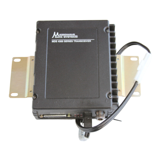
Microwave Data Systems MDS 4310 Installation, Operation & Field Maintenance (129 pages)
350–512 MHZ RADIO TRANSCEIVER
Brand:
Microwave Data Systems
| Category:
Transceiver
| Size: 0 MB
Table of Contents
Table of Contents
6
Chapter 1-General
14
Introduction
14
Applications
14
Terms "Analog" and "Digital
15
Mds 4310 Modulation Techniques
15
Microcontroller Features
15
Soft Carier Dekey
16
Control Inputs and Outputs
16
Model Number Codes
17
Figure 1-1. MDS 4310 Model Number Codes
17
Specifications
18
Figure 1-2. Printed Circuit Model Number Location
18
OPTIONAL EQUIPMENT, ACCESSORIES and CERTIFICATIONS
23
Special Certifications
23
1200 BPS Bell 202T Modem
24
4800 BPS Modem
24
Audio Processing Module
24
Order Wire Module
24
Remote Maintenance Module (Internal)-P/N 03-1958A01
24
Hand-Held Terminal
25
RS-232 to RS-422 Converter Assembly-P/N 01-2358A01
25
TTL to RS-232 Converter Assembly
26
Figure 1-3. MDS 4310 Transceiver-Major Assemblies
26
Chapter 2-Installation
28
Overview
28
Surface Mounting
29
Figure 2-1. Mounting Dimensions-Front View
30
Figure 2-2. Mounting Dimensions-Bottom View
30
External Connections
31
ANTENNA Connector
31
INTERFACE Connector
31
Figure 2-3. External Connections
32
Table 2-1. DB-25 Interface Connector Pin Functions
33
INTERFACE Connector Pin Functional Descriptions
34
Figure 2-4. Received Signal Strength Indicator Calibration Chart (Typical)
37
Front Panel Indicators
38
Transceiver Configuration Jumpers
39
Figure 2-5. Location of Configuration Jumpers
39
J14-Receiver Audio Output Phase
40
J16-Full Duplex Option Connector
40
Modems-General
40
Introduction
40
Table 2-5. J14 Receiver Audio Output Normal/Inverted
40
Figure 2-6. Detail of Configuration Jumpers-J14
40
The Role of the Modem
41
RTS and CTS Signals
41
DCD Signal
41
Power Requirements
41
Antennas and Feedlines
42
Antenna Selection and Mounting
42
Feedline Selection
43
Table 2-6. Signal Loss Versus Cable Length and Type
43
Feedline Installation
44
Figure 3-1. Hand-Held Terminal Connected to the MDS 4310 Transceiver
47
Figure 3-2. MDS 4355 Packaged Transceiver
47
Figure 3-2. Hand-Held Terminal Keypad
51
Table 3-1. Diagnostic and Control Capabilities
55
Table 3-2. Programming and Test Commands
56
Figure 3-3. HHT Initialization Display
58
Table 3-3. Hand-Held Terminal Operating Defaults
59
Figure 3-4. DB-25 Interface Adapter Wiring
59
Figure 3-5. DB-9 to DB-25 Interface Cable Wiring
60
Figure 3-6. DB-25 to DB-25 Interface Cable Wiring
60
Figure 4-1. Remote Data Terminal Emulator Wiring
65
Figure 4-2. Construction Options for Building a Data Terminal Emulator
65
Table 4-1. Main Circuit Board Potentiometer Settings for Remote Maintenance
67
Table 4-2. Test Procedure Reference Chart
67
Appendix H-Mds 4310-Hl
68
Introduction
68
Figure 4-3. VCO Lock Voltage Test Point
70
Figure 4-4. 1200 Bps AFSK Modem
74
Configuration
76
Figure 4-5. 4800 BPS FSK Modem
76
Figure 4-7. Remote Maintenance Module
80
Figure 4-8. Remote Maintenance Screen
84
Figure 5-1.MDS 4310 Transceiver Block Diagram
94
Figure A-1. 1200 Bps Modem PC Board
100
Figure A-2. Bell 202T Compatible Modem Block Diagram
102
Figure B-1. MDS 4800 Bps Modem Block Diagram
105
Table B-1. Settings for the MDS 4800 Bps Modem's Configuration Switch S1
106
Figure B-2. MDS 4800 Bps Modem Assembly Diagram
106
Table C-1. Settings for the MDS 9600 Bps Modem's Configuration Switch S1
109
Figure C-1. MDS 9600 Bps Modem Block Diagram
110
Figure C-2. 9600 Bps Modem Assembly Diagram
110
Figure D-1. Remote Maintenance Module, P/N 03-1958A01
113
Figure E-1. Order Wire Module
118
Figure E-2. Order Wire Board Component Layout
119
Conditions of Approval
122
Appendix Icanadian Certification
124
Rss Approvals
124
Restrictions
124
Appendix Jaudio Processing Module
126
Introduction
126
Specifications
126
Alignment
127
Table J-1. P/N 03-2301A01 Configuration Switch Settings
127
Advertisement
Advertisement
Related Products
Microwave Data Systems MDS 9810
Microwave Data Systems MDS TransNET 900
Microwave Data Systems MDS 1710 A
Microwave Data Systems MDS 1710 C
Microwave Data Systems MDS 2710A
Microwave Data Systems MDS 2710C
Microwave Data Systems MDS 2710D
Microwave Data Systems MDS FIVE Series
Microwave Data Systems EL805
Microwave Data Systems iNET 900 Series
Microwave Data Systems Categories
Transceiver
Radio
More Microwave Data Systems Manuals
Login
Sign In
OR
Sign in with Facebook
Sign in with Google
Upload manual
Upload from disk
Upload from URL