Sign In
Upload
Manuals
Brands
Global American Manuals
Motherboard
3308490
Global American 3308490 PCISA Atom Manuals
Manuals and User Guides for Global American 3308490 PCISA Atom. We have
1
Global American 3308490 PCISA Atom manual available for free PDF download: User Manual
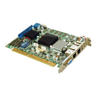
Global American 3308490 User Manual (102 pages)
Half-Size PCISA SBC with Intel Atom N270 Processor
Brand:
Global American
| Category:
Motherboard
| Size: 9 MB
Table of Contents
Table of Contents
4
1 Introduction
14
Figure 1-1: 3308490
15
Figure 1-2: 3308490 Overview (Front)
16
Figure 1-3: 3308490 Overview (Rear)
17
Technical Specifications
18
Table 1-1: Technical Specifications
20
Peripheral Connectors and Jumpers
17
Introduction
15
Overview Photo
16
2 Detailed Specifications
21
Dimensions
22
Board Dimensions
22
Figure 2-1: 3308490 Dimensions (MM)
22
Figure 2-2: External Interface Panel Dimensions (MM)
23
Figure 2-3: Data Flow Block Diagram
24
Features
25
Figure 2-4: CPU and Northbridge Connections
25
Intel ® Atom ™ Processor
25
Overview
25
DDR2 Controller
26
Front Side Bus (FSB)
26
Intel® 945GSE Northbridge Chip
26
Analog CRT (VGA)
27
Graphics
27
Lvds
27
TV out
27
Intel® ICH7M Southbridge Chipset
28
SDVO and DVI
28
Figure 2-5: Intel® ICH7M Southbridge Connections
29
HD Audio Controller
30
IDE Interface
30
Compactflash® Slot
31
IDE Connector
31
Real Time Clock
31
Table 2-1: Supported HDD Specifications
31
Ite IT8718F Super I/O Chipset
32
SATA Controller
32
USB Controller
32
16C550 Uarts
33
Figure 2-6: Super I/O Connections
33
LPC Interface
33
Digital Input/Output
34
Enhanced Hardware Monitor
34
Fan Speed Controller
34
Keyboard/Mouse Controller
34
Parallel Port
34
PCI Bus
34
Gigabit Ethernet Connector
35
ISA Edge Connector
35
PCI Edge Connector
35
Pcie Bus
35
Spi Bios
36
SPI Bus Components
36
Environmental and Power Specifications
37
Operating Temperature and Temperature Control
37
System Monitoring
37
Power Consumption
38
Table 2-2: Power Consumption
38
Data Flow
24
External Interface Panel Dimensions
23
3 Unpacking
39
Anti-Static Precautions
40
Unpacking
40
Unpacking Precautions
40
Unpacking Checklist
41
Package Contents
41
Optional Items
42
Table 3-1: Packing List
42
Table 3-2: Power Consumption
43
4 Connectors
44
Figure 4-1: Connector and Jumper Locations [Front Side]
45
Figure 4-13: IDE Device Connector Locations
59
Figure 4-14: Infrared Connector Pinout Locations
60
Figure 4-15: Keyboard/Mouse Connector Location
61
Keyboard/Mouse Connector
61
LVDS LCD Connector
61
Table 4-15: Keyboard/Mouse Connector Pinouts
61
Figure 4-16: LVDS LCD Connector Pinout Locations
62
Figure 4-17: SATA Drive Connector Locations
63
SATA Drive Connectors
63
Table 4-16: LVDS LCD Port Connector Pinouts
63
Figure 4-18: Parallel Port Connector Location
64
Parallel Port Connector
64
Table 4-17: SATA Drive Connector Pinouts
64
Figure 4-19: RS-232 Connector Pinout Locations
65
Serial Port Connector (RS-232)
65
Table 4-18: Parallel Port Connector Pinouts
65
Figure 4-20: RS-232/422/485 Connector Pinout Locations
66
Serial Port Connector (RS-232/422/485)
66
Table 4-19: RS-232 Connector Pinouts
66
Table 4-20: RS-232/422/485 Connector Pinouts
66
Figure 4-21: SDVO Connector Pinout Locations
67
SDVO Connector
67
Table 4-21: SDVO Connector Pinouts
68
TV out Connector
68
Figure 4-22: TV Connector Pinout Locations
69
Table 4-22: TV Port Connector Pinouts
69
USB Connectors
69
External Peripheral Interface Connector Panel
70
Figure 4-23: USB Connector Pinout Locations
70
Table 4-23: USB Port Connector Pinouts
70
Figure 4-24: 3308490 External Peripheral Interface Connector
71
Figure 4-25: LAN Connector
71
LAN Connectors
71
Table 4-24: LAN Connector Pinouts
71
Table 4-25: LAN Connector Leds
72
Table 4-26: USB Port Pinouts
72
USB Connectors
72
VGA Connector
72
Figure 4-26: VGA Connector
73
Table 4-27: VGA Connector Pinouts
73
Infrared Interface Connector
60
Table 4-13: IDE Connector Pinouts
60
Table 4-14: Infrared Connector Pinouts
60
Peripheral Interface Connectors
45
Layout
45
Figure 4-2: Connector and Jumper Locations [Solder Side]
46
Figure 4-3: ATX Power Supply Enable Connector Location
48
Figure 4-4: Audio Connector Location (9-Pin)
49
Table 4-3: ATX Power Supply Enable Connector Pinouts
49
Backlight Inverter Connector
50
Figure 4-5: LCD Backlight Connector Pinout Locations
50
Table 4-4: Audio Connector Pinouts (9-Pin)
50
Table 4-5: LCD Backlight Connector Pinouts
50
Battery Connector
51
BIOS Programming Connector
51
Figure 4-6: Battery Connector Location
51
Table 4-6: Battery Connector Pinouts
51
Compactflash® Socket
52
Figure 4-7: BIOS Programming Connector Pinouts
52
Table 4-7: BIOS Programming Connector
52
Figure 4-8: CF Card Socket Location
53
Digital I/O Connector
54
Figure 4-9: Digital I/O Connector Locations
54
Table 4-8: CF Card Socket Pinouts
54
Fan Connector
55
Figure 4-10: CPU Fan Connector Location
55
Table 4-10: CPU Fan Connector Pinouts
55
Table 4-9: DIO Connector Pinouts
55
Figure 4-11: Floppy Disk Connector Location
56
Floppy Disk Connector
56
Front Panel Connector
57
Table 4-11: Floppy Disk Connector Pinouts
57
Figure 4-12: Front Panel Connector Pinout Locations
58
IDE Connector
58
Table 4-12: Front Panel Connector Pinouts
58
Audio Connector
49
Internal Peripheral Interface Connectors
46
External Interface Panel Connectors
47
Table 4-1: Peripheral Interface Connectors
47
Table 4-2: Rear Panel Connectors
47
Internal Peripheral Connectors
48
ATX Power Control Connector
48
5 Installation
74
Anti-Static Precautions
75
Installation Considerations
76
Installation Notices
76
Installation Checklist
77
Unpacking
77
Cf Card Installation
78
Atx Power Control Connector
79
Figure 5-1: CF Card Installation
79
Figure 5-2: ATX Power Control Connector
80
Figure 5-3: Jumper Location
82
Clear CMOS Jumper
83
Table 5-2: AT/ATX Power Selection Jumper Settings
83
Table 5-3: Clear CMOS Jumper Settings
83
CF Card Setup
84
COM2 RS-232/422/485 Selection Jumper
84
Table 5-4: CF Card Setup Jumper Settings
84
Table 5-5: COM2 RS-232/422/485 Selection Jumper Pinouts
84
LCD Panel Type Selection
85
LVDS Voltage Selection
85
Table 5-6: LCD Panel Type Selection Jumper Settings
85
Airflow
86
Chassis Installation
86
Table 5-7: LVDS Voltage Selection Jumper Settings
86
Channel Audio Kit Installation
87
Internal Peripheral Device Connections
87
Motherboard Installation
87
Table 5-8: GAI Provided Cables
87
Figure 5-4: 5.1 Channel Audio Kit
88
Channel Audio Kit Installation
89
ATA Flat Cable Connection
90
Figure 5-5: 7.1 Channel Audio Kit
90
Dual RS-232 Cable with Slot Bracket
91
Figure 5-6: IDE Cable Connection
91
Figure 5-7: Dual RS-232 Cable Installation
92
Figure 5-8: FDD Cable Connection
93
Parallel Port Cable Without Bracket
93
Figure 5-9: LPT Cable Connection
94
SATA Drive Connection
94
Figure 5-10: SATA Drive Cable Connection
95
Figure 5-11: SATA Power Drive Connection
96
USB Cable (Dual Port) with Slot Bracket
96
Figure 5-12: Dual USB Cable Connection
97
External Peripheral Interface Connection
98
Figure 5-13: Connect the LPT Device
98
LAN Connection
98
Figure 5-14: LAN Connection
99
USB Device Connection (Single Connector)
99
VGA Monitor Connection
100
Floppy Drive Cable Connection
92
Jumper Settings
81
Table 5-1: Jumpers
81
AT/ATX Power Selection
82
Figure 5-15: USB Device Connection
100
Figure 5-16: VGA Connector
101
Advertisement
Advertisement
Related Products
Global American 3308040B
Global American 3308040D
Global American 3308040E
Global American 3308040F
Global American 3308040G
Global American 3308040H
Global American 3308050A
Global American 3308050B
Global American 3308180
Global American 3308540
Global American Categories
Motherboard
Single board computers
Computer Hardware
Controller
Desktop
More Global American Manuals
Login
Sign In
OR
Sign in with Facebook
Sign in with Google
Upload manual
Upload from disk
Upload from URL