Table of Contents
Advertisement
Advertisement
Table of Contents

Related Manuals for Berthold LB 444 K-40


Summary of Contents for Berthold LB 444 K-40
- Page 1 Potassium Content Measurement LB 444 K-40 ID No. 55884BA2 Rev. Nr.: 00...
-
Page 3: Table Of Contents
Installation of the Detector ..............10 4.7.1 Installation in a Container .............. 10 CONNECTIONS ..............11 5.1.1 Evaluation Unit LB 444 K-40 ............11 Evaluation Unit LB 444 K-40 ..............13 5.2.1 General Description ............... 13 5.2.2 Display ..................13 5.2.3 Keypad Function ................ - Page 4 Detector ....................50 10.3.1 Checking the Crystal-Multiplier Assembly ......... 50 10.3.2 Testing and replacement of the photomultipliers in the detector LB 543051 10.4 Replacing the Evaluation Unit LB 444 K-40........... 52 10.5 Setup Protocol ..................53 DIMENSIONAL DRAWINGS ..........55 11.1 LB 5402 ....................
- Page 5 01/10 LB 444 K-40 Operating Manual Potassium Meter LB 444 K-40 Issue Date Comments 01.01.10 First edition...
-
Page 7: General Information
01/10 LB 444 K-40 General Information Safety Summary Electrical Shock Hazard Disconnect power to ensure that contact with energized part is avoided during installation and servicing. Specific Warnings Never change the installation or the parameter settings without a full knowledge of the relevant part of this manual, the connected controller and the process, if it is controlled by this measuring device. -
Page 8: Overview
01/10 LB 444 K-40 Overview The Potassium Meter LB 444 K-40 is designed for measurements of the concentration of potassium in bulk materials, suspensions and solutions. The concentration of potassium in bulk materials or liquid solutions is measured by detecting gamma radiation of the natural isotope K-40. This isotope is contained in natural potassium in a constant percentage (0.0119%). - Page 9 01/10 LB 444 K-40 The hardware and software of the LB 444 K-40 system makes it easy to adapt the system to rather different measuring geometries and measuring tasks. Therefore, the settings and parameters of the measuring instrument have to be defined with care for the respective measuring task when taking the system into operation.
-
Page 10: System Description
A 19” rack can be supplied for installation of up to 4 devices or a protective housing for two devices for installation of the evaluation unit. The device LB 444 K-40 with a software that has been expanded for potassium content measurements is used as evaluation unit. The functions of the density measurement are still available. -
Page 11: Installation Of The Detectors
01/10 LB 444 K-40 Installation of the Detectors 4.1 Selection of the Measuring Site Assuming a homogeneous mixture of potassium in the material to be measured, the number of K-40 isotopes increases with increasing amount of material. This means that the count rate of the detector rises when the amount of material in front of the detector rises, although the material contains a constant percentage of the K-40 isotope. -
Page 12: Installation Of The Detector Lb 5430 On A Bunker
01/10 LB 444 K-40 2 = material not covered by the measurement 4.2 Installation of the Detector LB 5430 on a Bunker The LB 5430 detector is installed on the outside wall of a bunker. Typically, it is fixed to the flange of the detector. -
Page 13: Installation Of The Detector Lb 5402 In A Bunker
01/10 LB 444 K-40 4.3 Installation of the Detector LB 5402 in a Bunker The detector is installed into a protective pipe, front side closed, and inserted into a bunker. The distance of the material surface in front of the detector head sensitive to radiation (position of the scintillation crystal) should on all sides correspond to the calculated saturation thickness. - Page 14 01/10 LB 444 K-40 A correction function can then be calculated from these values. Figure 5: Measurement in a pipeline Potassium measurement. Saturation thickness for different densites resp. bulk densities Density =1,4 Density =1,0 Density =1,2 1000 Layer thickness in mm...
-
Page 15: Measurement On A Conveyor Belt
01/10 LB 444 K-40 The detector should be mounted in a horizontal pipeline at the top or side. This will prevent that the measurement is influenced by any deposits on the ground of the pipeline. 4.5 Measurement on a Conveyor Belt... -
Page 16: Installation Of The Evaluation Electronics
01/10 LB 444 K-40 4.6 Installation of the Evaluation Electronics The evaluation unit (protection type IP 20) can be installed in a 19” rack. This rack then has to be installed into a suitable measurement cabinet. The wall housing can be fixed directly to a wall using screws. For outdoor installation, you may have to install a sunshield to protect the evaluation unit against solar heating. -
Page 17: Connections
The power supply of the detector and the transfer of the measured values and important information to the evaluation unit LB 444 K-40 takes place via a two-wire screened cable. The possible cable length is dependent on the cross-section of the connection cable used. - Page 18 01/10 LB 444 K-40 Detector (2a/2c) Relay 2 (12a/12c) The relay can be set for the following functions: Min. – Alarm, Max. – Alarm, Detector temperature, Relay 3 (4a/14c) Functions: Min. – Alarm, Max. – Alarm, Detector temperature, Relay 1 (16a/16c) The relay is used to indicate errors.
-
Page 19: Evaluation Unit Lb 444 K-40
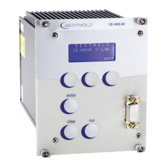
01/10 LB 444 K-40 5.2 Evaluation Unit LB 444 K-40 5.2.1 General Description The evaluation electronics is designed as a 19” module in the format 3 HE, 21 TE. It BERTHOLD includes the microprocessor- LCD display LB 444 - 1 V 1.0... -
Page 20: Softkeys
01/10 LB 444 K-40 5.2.4 Softkeys Softkeys are used to select different menu groups and operating levels within the menu structure. Depending on the current position in the menu structure, functions are assigned to these keys, as shown on the display above the respective key. -
Page 21: Menu Potassium Content Measurement
01/10 LB 444 K-40 Enter Accepts the entry and moves the cursor to the next input field or toggles between two input fields. sk1 : General Data sk2 : Operating Mode more Starts or stops a measurement or leads directly back to the display and... - Page 22 Measuring Path Berthold Curr. Output Limits Solid density Value: 54321 cps Backscatter measure Value : 10,0 cm Value: 2.6500 g/cm3 LB 444 K-40 V. X.XX 0/4 mA 1,0000 K20/KCl Density - Meter 20 mA 1,2000 Coefficient Liquid density Select: Measure Mode Error mode Relais Nr.
- Page 23 01/10 LB 444 K-40 sk1: Service Menu sk2: Mass Flow Page 16 sk1: HV Adjustment sk1: Reset Detector sk1: Plateau sk1: Adj. Cur. input sk1: Test calculate sk2: Status request sk2: Pt 100 adjust sk 2: Adj. Current out sk 2: Relay Delaytime...
- Page 24 01/10 LB 444 K-40 sk1: Service Menu sk1:Calibrate sk2:Live Display sk2: Mass Flow more more sk1: Interface L B 4 4 4 DENSITY more 1.2345 g/cm3 Interface RS 232: Printer/PC Value: 1.2345 g/cm3 RS 485 Printer/LB 447 Temperature: 45.2 °C more 1.2345 g/cm3...
-
Page 25: Software Functions And System Configuration
01/10 LB 444 K-40 Software Functions and System Configuration Depending on the selected configuration, some input dialog boxes are dimmed. In chapter 5.2.5 you find an overview of the menu structure After commissioning, enter the final operating settings in the Configuration list in the Appendix. -
Page 26: Operating Mode
Select device to which data is to be transferred: select either PC, printer or modem. Terminal program settings: In LB 444 K-40: Printer In terminal program: 9600 baud, 8 data bit, 1 stop bit, no parity, protocol: X on / X off. -
Page 27: Parameter
01/10 LB 444 K-40 6.3 Parameter Measuring product No. 1/2/3/4: Parameters (detector type, current output range, limit values, etc.) for up to 4 different products can be entered and stored. These parameters have to be entered separately for each product. - Page 28 01/10 LB 444 K-40 Rapid switchover: This function (= 1/10 of defined time constant) is needed to adjust the ON / OFF: output signal quickly to the new value if sudden Concentration changes occur. This function is not used for potassium content measurements.
-
Page 29: Product Data
01/10 LB 444 K-40 6.4 Product Data Enter product data for parameter setup and calibration separately for each product. Product selection No. 1/2/3/4: Enter product number for calibration. Current Output: Select current output signal 0 or 4 mA. Current Output Limits:... -
Page 30: Calibrate
01/10 LB 444 K-40 6.5 Calibrate Background for rod detector Product selection No. 1/2/3/4: Select product to be calibrated and confirm with <enter>. Suspension measure <enter>. Unit select g/cm³, t/m³,Bx, weight %, °Be, g/l, mm, g/m , % K Select the unit for concentration measurement and area weight measurements (mm, g/m²). - Page 31 01/10 LB 444 K-40 values will not be saved. Count rate in cps is read-in or entered. Rate: Enter the concentration value %K20 determined in the lab. Concentration: sk2: Calculate Calibrate mode Select the calibration mode: on/lin/squ/cub/auto (see also 6.5 and 7.2.2).
-
Page 32: Live Display
01/10 LB 444 K-40 This value is calculated automatically for two- or multi-point calibration. It indicates the quality of the calibration curve for the selected calibration mode. The smaller the numerical value, the better the curve fit. Factor Enter a multiplication factor (0 to 10) to correct the measured values. Each measured value is multiplied by this factor. -
Page 33: Getting Started
° Install water cooling if temperatures exceed >50 Install evaluation unit. Connect detector to LB 444 K-40 via two-wire cable. Connect cable to terminal 2a and 2c of evaluation unit. External product selection With the external product selection you can measure up to 4 different products. -
Page 34: Getting Started
01/10 LB 444 K-40 7.2 Getting Started 7.2.1 Basic Settings These steps describe how to take the system into operation and how to change the basic system settings. Note: To enter numbers, select the entry position with <←←←> and the number you want with <^^^>. -
Page 35: Calibration
01/10 LB 444 K-40 3.2 Push <sk2> to select Product Data and <more> to call parameters sequentially. Select product: “1” Select current output 0 –20 or 4 – 20 mA Define current output limit values 0/4 and 20 mA: x% K20 = 4 mA y% K20 = 20 mA Define behavior of the current output in case of error message. - Page 36 01/10 LB 444 K-40 e) with product in the vessel which does not contain any potassium or f) dismounted detector arranged on a concrete floor or min 20 mm lead or 40 mm steel plate in front of the radiation window.
-
Page 37: Checking The Calibration
01/10 LB 444 K-40 linear <enter>. The calibration is carried out. The coefficient is calculated by the program. The calculated zero count rate Io and the coefficient a1 and the square error are displayed. If necessary, enter a factor, by which the measured values are multiplied. -
Page 38: Correcting The Results: Addition And Multiplication
01/10 LB 444 K-40 Push +….- to call further value • current measured value in the selected unit • averaged count rate (averaging according to entered time constant) • actual count rate • display of the adjusted high voltage 7.4 Correcting the Results: Addition and Multiplication This option should not be regarded as a substitute for careful calibration. -
Page 39: Automatic Measuring Time Switchover
01/10 LB 444 K-40 − − − − actual actual Input value for Offset: − − − actual H = upper value of the measuring range in g/cm H = lower value of the measuring range in g/cm The same is true if upper and lower point of the measuring range are to be changed by different values. -
Page 40: Batch Measurement
01/10 LB 444 K-40 Response 1 Density value 2 Signal trend with 3 Signal trend without automatic switchover of time constant -3 2 7 12 17 22 27 32 37 42 47 52 57 62 67 72 77 82 87 92 97... -
Page 41: Radiating Interference Detection
01/10 LB 444 K-40 The measurement is started in the batch mode by pushing the <run> button and stops automatically when the entered time is over or briefly (>1s) connecting the terminals 26a and 26c. Once the entered time is over, the measurement is stopped automatically. -
Page 42: Error Messages
01/10 LB 444 K-40 7.8 Error Messages 7.8.1 Acknowledging Error Messages All error messages must be reset with <enter>. Several simultaneously or consecutively occurring errors are stored in an error register in the order of their appearance; they have to be reset individually by pushing <enter>... -
Page 43: Error Messages During Measurement
01/10 LB 444 K-40 7.8.4 Error Messages during Measurement Error Message Cause, Remarks Remedy Rate Overflow Count rate > 520000 High voltage wrong. Replace detector No Detector Rate Detector faulty Replace detector Wrong HV Detector faulty Replace detector Pt 100 wrong... - Page 44 01/10 LB 444 K-40 Message Cause, Remarks Measurement halted Measurement process stopped via digital input <HALT> measurement stopped because count rate threshold has been exceeded or not reached. Rate Overflow Detector faulty. High voltage outside of the plateau. Power Fail Complete failure or drop of power supply below tolerance level.
-
Page 45: System Start/Stop
01/10 LB 444 K-40 7.9 System Start/Stop To stop operation of the measuring system, proceed as follows: Turn system off. The water cooling device has to be used if the detector temperature may rise above 50°C even though the instrument is not in operation. -
Page 46: Technical Data
01/10 LB 444 K-40 Technical Data 8.1 Evaluation Unit LB 444 K-40 Assembly: 19” module 3 HE, 21 TE; protection type IP 20 Power supply: 115 V ± 10%, 230 V ± 10%, 18-32 V AC/DC Power consumption: approx. 30 V or 30 W Temperature range: Operating temperature: 0 - 50 °C;... -
Page 47: Detectors
01/10 LB 444 K-40 DC: Max. 300V, max. 1A, max. 60 W non-reactive load Current input: 0/4 - 20 mA isolated for input of temperature signal or volume current signals Interfaces: RS 232. Port for data transfer from evaluation unit to printer or PC 8.2 Detectors... -
Page 48: Service Instructions
Please refer to the Safety Summary at the beginning of this operating manual. 9.2 Evaluation Unit LB 444 K-40 The evaluation unit is provided with an error control which also monitors the detector functions. An error code appears on the display if an error is detected. For information about the error and possible causes please refer to the error code list. - Page 49 01/10 LB 444 K-40 I.Max/I.Min value Current output entered incorrectly Current input error Current input range entered incorrectly Current output limit value Current output range entered incorrectly Current input error Current input too high > 20mA Device not calibrated Calibration has to be terminated with <enter>...
-
Page 50: Service
01/10 LB 444 K-40 10 Service 10.1 Service Menu Overview... - Page 51 01/10 LB 444 K-40 sk1: Service Menu sk2: Mass Flow more sk1: HV Adjustment sk1: Reset Detector sk1: Plateau sk1: Adj. Cur. input sk1: Test calculate sk2: Status request sk2: Pt 100 adjust sk 2: Adj. Current out sk 2: Relay Delay time...
-
Page 52: Service Menu
01/10 LB 444 K-40 10.2 Service Menu The Service menu functions support input of test values (output current, count rates) to simulate instrument functions • check of outputs and inputs adjustment of analog outputs and inputs adjustment of Pt 100 input (N/A) •... -
Page 53: Plateau Check
It is also possible that the specific Gamma sensitivity appears to have changed or obvious instabilities are apparent. This error can be detected only by means of a plateau check. The evaluation unit LB 444 K-40 includes a function for automatic plateau recording. - Page 54 01/10 LB 444 K-40 irrelevant. 16000 14000 12000 10000 8000 6000 4000 2000 1000 1100 1200 1300 HV in V Figure 14: Plateau curve with Na I crystal (LB 5402) Plateau LB 5430 50000 45000 Setpoint of the HV control...
- Page 55 01/10 LB 444 K-40 multiplier combination have to be replaced. Request Plateau The value pairs of the plateau measurement may be displayed here and may be plotted to assess the curve. Adjust current output Current 1.8 or 18 mA: Adjustment of output current to the values 1.8 mA and 18 mA by incrementing or decrementing the numerical value on the display.
-
Page 56: Detector
01/10 LB 444 K-40 10.3 Detector 10.3.1 Checking the Crystal-Multiplier Assembly A plateau that is too small or too steep indicates faults in the crystal-multiplier assembly. Please proceed as follows to perform a visual inspection of crystal and multiplier: Switch off the scintillation counter before opening the instrument. - Page 57 The organic scintillator is in the front housing part of the detector LB 5430 (1 in Fig. 17 ). This housing should only be opened by the service staff from Berthold. The detector electronics and the photomultiplier are located in the rear housing part (2 in Fig.
-
Page 58: Replacing The Evaluation Unit Lb 444 K-40
6. Screw on lid. 10.4 Replacing the Evaluation Unit LB 444 K-40 To replace the entire LB 444 K-40 evaluation unit, please proceed as follows: Connect new evaluation computer. In submenu Calculate (menu Calibrate), select the calibration mode (K2O). Enter data using the set-up protocol and date of the original set-up. -
Page 59: Setup Protocol
01/10 LB 444 K-40 10.5 Setup Protocol Measuring Point ..........Date: ......Product: ............Parameter Range Value Password Instrument ID Program version Configure instrument Radiation measure yes / no Error mode Hold/continue Product no. 1/2/3/4 Measuring path Measure mode Time constant... - Page 60 01/10 LB 444 K-40 Parameter Range Value Relay 2 setup Min or Max: Hysteresis : 0-10% Relay 3 setup Min or Max: Hysteresis : 0-10% Data input: ° Count rate cps Concentration (lab values) Date Temperature Calculation: Parameter Range Value...
-
Page 61: Dimensional Drawings
01/10 LB 444 K-40 11 Dimensional Drawings 5402 Cable gland M16 11.1 for cable dia. 7-10 mm Weight approx. 6 kgs approx. 40 dia. dia. 75.5 11.2 LB 5430 LB 5430 Weight appr. 52 kg... -
Page 62: Lb 444 K-40
01/10 LB 444 K-40 11.3 LB 444 K-40 19” module Installation in 19” rack Installation in wall housing... - Page 63 01/10 LB 444 K-40 0 V (+ 24 V) + 24 V...
- Page 64 01/10 LB 444 K-40...
Need help?
Do you have a question about the LB 444 K-40 and is the answer not in the manual?
Questions and answers