Table of Contents
Advertisement
Quick Links
Advertisement
Table of Contents

Related Manuals for GEZE Perlan AUT-NT


Summary of Contents for GEZE Perlan AUT-NT
- Page 1 GEZE Perlan GB Wiring diagram AUT-NT...
-
Page 2: Table Of Contents
GEZE Perlan AUT-NT Table of contents Symbols and means of representation ......................3 Warnings ..........................................3 Further symbols and means of representation .............................3 Validity ..................................3 Product liability ................................3 Notes ....................................3 Important safety instructions ..................................3 Mounting instructions ....................................4 Safety-conscious working .....................................4 Checking the mounted system ...................................4 Disposing of the door system ..................................4... -
Page 3: Symbols And Means Of Representation
à GEZE shall not be liable for injuries or damage resulting from unauthorised modification of the equipment. à GEZE shall not be liable if products from other manufacturers are used with GEZE equipment. Use only origi- nal GEZE parts for repair and maintenance work as well. -
Page 4: Mounting Instructions
Notes GEZE Perlan AUT-NT à In accordance with Machinery Directive 2006/42/EC, a safety analysis must be performed and the door system identified in accordance with CE Identification Directive 93/68/EEC before the door system is commissioned. Enter the classification in accordance with DIN 18650-1 on the information plate and adhere the information plate onto the drive housing so that it is visible from below. -
Page 5: Abbreviations
GEZE Perlan AUT-NT Abbreviations Abbreviations Wire colours brown green orange turquois black grey pink violet blue yellow WH white Connections, terminals and plugs Reference potential Motor Rotary transducer Motor Contactor STOP Stop Contactor close Supply terminals CAUTION! Destruction of the component through incorrect connection. -
Page 6: Mounting Of The Components
à Controller at the door in surface-mounted box à Controller installed externally (e.g. wall recess, control cabinet …) à Connection variants for power pack Perlan AUT-NT à Power pack at the door in flush-mounted box à Power pack at the door in surface-mounted box... -
Page 7: Requirement
à Mounting height for controller: from 850 mm to maximum 1200 mm above the top edge of the completed flooring Mounting the flush-mounted controller and power pack The instructions describe the mounting recommended by GEZE of a connection variant with flush-mounted controller and power pack. Lay the 24-V output cable of the power pack into the flush-mounted box (1). - Page 8 Mounting of the components GEZE Perlan AUT-NT Insert the power pack (3) into the flush-mount- ed box (1). Connect the power supply cable to the fusing terminal strip (7) of the power input line of the power pack.
- Page 9 GEZE Perlan AUT-NT Mounting of the components Connect the motor connection cable to the controller (2) in accordance with the wiring diagram. Mount the controller (2) in the flush-mounted box (1).
-
Page 10: Contactors
9. 1 Radar movement detector GC 302 R à An additional power pack 230 V / 24 V Perlan AUT-NT is required to supply external actuation elements. Take the maximum permissible current draw into account when an additional power pack is used (500 mA). -
Page 11: Switch (Floating Contact)
Power supply cable 230 V / 50 Hz Mains fuse 10 A by customer, with all-pole discon- nection Fuse terminal strip 2.5 mm² with glass fuse 5×20 mm, T2A Power pack 230 V / 24 V, Perlan AUT-NT, GC 302 R Mat. No. 139994 Conductor terminal strip, 2-pole, 1.5 mm² 50 mA Controller Set the detection field and sensitivity of the radar movement detector. -
Page 12: Radio Control
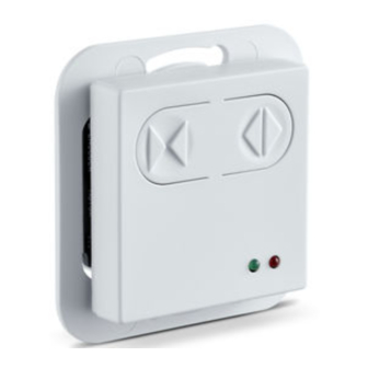
Contactor close GEZE Perlan AUT-NT Radio control Observe the mounting and service instructions of the GEZE Automatic Radio Program, Mat. No. 132159. à Radio transmitter module WTM, Mat. No. 131212 à Hand-held radio transmitter WTH-1, Mat. No. 131209 à Hand-held radio transmitter WTH-2, Mat. -
Page 13: Operating Mode
GEZE Perlan AUT-NT Operating mode Operating mode 13. 1 Setting the operating mode The operating mode of the sliding door drive has to be set during commissioning (see Chapter 17). 13.2 Operating modes Dead-man The drive continues to move in the direction as long as its button is pressed or the signal is applied. -
Page 14: Behaviour In The Individual Operating Modes
Operating mode GEZE Perlan AUT-NT 13.4 Behaviour in the individual operating modes Automatic OPEN button CLOSE button STOP button Obstacle Closed Open, wait for hold- Door remains closed, in- open time, close active until stop button. An OPEN button actua- tion remains stored for 20 s. -
Page 15: Mains Connection
Mains fuse (provided by customer) Master switch (provided by customer) Emergency-off (optional) Fuse terminal strip 2.5 mm with glass fuse 5×0 mm T2A Power pack 230 V / 24 V Perlan AUT-NT, Mat. No. 139994 Controller NT Motor Motor-gearing unit, Mat. No. 139992 Low-energy operation Low-energy doors are as a rule not equipped with additional protective devices, since the kinetic energy values are viewed as harmless. -
Page 16: Commissioning And Service
Commissioning and service GEZE Perlan AUT-NT Commissioning and service The following sections describe the parts of the controller which are required for commissioning, the functions which have to be set and how to carry out the commissioning step-by-step. – LEDs for status display... -
Page 17: Configuration
GEZE Perlan AUT-NT Commissioning and service à Speed (6 to 8) The speed has to be set on the basis of the leaf weight. à (6) Leaf weight 80 kg–60 kg (approx. 70% of the maximum speed) 0.20 m/s à (7) Leaf weight 60 kg–40 kg (approx. 85% of the maximum speed) 0.23 m/s... -
Page 18: Steps For Commissioning
Commissioning and service GEZE Perlan AUT-NT 17.2 Steps for commissioning CAUTION! Danger of injury from moving door leaves. The door leaves move during commissioning. Leave the danger area. Preparing the controller Carry out the electrical connections (see Chapter 6). Set the configuration (see Chapter 17.1). -
Page 19: Error Display
GEZE Perlan AUT-NT Error display Error display If the safety functions recognize a fault, the controller changes to the fault state. In this case the driver block and the safety relay are deactivated first. The following system states have been defined for the fault recognition:... - Page 20 GEZE India Private Ltd. 2630 Taastrup China Niederlassung West MF2 & 3, Guindy Industrial Estate Tel. +45(0)46-323324 Nordsternstraße 65 GEZE Industries (Tianjin) Co., Ltd. Ekkattuthangal Fax +45(0)46-323326 45329 Essen Shuangchenzhong Road Chennai - 600 097 E-Mail: danmark.se@geze.com Tel. +49 (0) 201-83082-0...
Need help?
Do you have a question about the Perlan AUT-NT and is the answer not in the manual?
Questions and answers