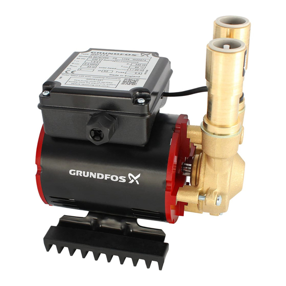
Grundfos STC Series Installation And Operating Instructions Manual
Shower pumps
Hide thumbs
Also See for STC Series:
- Instructions manual (20 pages) ,
- Installation and operating instructions manual (16 pages)
Table of Contents
Advertisement
Advertisement
Table of Contents

Subscribe to Our Youtube Channel
Summary of Contents for Grundfos STC Series
- Page 1 GRUNDFOS INSTRUCTIONS Shower pumps Installation and operating instructions...
- Page 2 Declaration of Conformity We, Grundfos, declare under our sole responsibility that the products SSL, STL, STC, SSR, STR, SSP, STP, SSN and STN, to which this declaration relates, are in conformity with these Council directives on the approximation of the laws of the EC member states: —...
-
Page 3: Table Of Contents
3.6 STC, STR, SSR, STL and SSL pumps These installation and operating instructions apply to the 3.7 Recommended installation Grundfos Shower Pumps, types STL, SSL, STC, STR, SSR, STP, Electrical connections SSP, STN and SSN. 4.1 Electrical connection, 1 x 230 V, 50 Hz For supplementary instructions regarding negative-head pumps, 4.2 Electrical connection, low-voltage pumps (STL, SSL... -
Page 4: Installation
3. Installation 3.2 Positioning the pump Select a position for installing the pump which 3.1 Important instructions affords easy access for subsequent servicing Note Do not connect the pump directly to the water and maintenance. mains supply. Minimum inlet head: 2 metres is recommended. The pump cannot be used with combination Keep the pump as close as possible to the source of hot and cold Caution... -
Page 5: Hot-Water Cylinder Connections
3.3 Hot-water cylinder connections 3.6 STC, STR, SSR, STL and SSL pumps The strainers supplied with the pump must be fitted to the pump Caution Do not use any jointing compounds. suction connections. See fig. 1. • Fit the plain hose washer to the discharge connection. The use of a Surrey flange (see fig. -
Page 6: Recommended Installation
3.7 Recommended installation System vent Cold-water supply connection to pump at least 25 mm Cold-water below cold-water supply connection to cylinder to storage tank of at prevent supply of hot water only least 50 gallons Highest point of pipework at least 250 mm (10 inches) below cold-water tank Shower See section 8. - Page 7 Cold-water supply to pump 22 mm service gate valves Supply to shower Cold Cold-water supply to cylinder Expansion pipe and Low-voltage pumps must be domestic hot-water supply connected via transformer only. Pump Surrey Hot-water supply flange to pump Hot-water Anti-gravity loop cylinder Hot-water cylinder thermostat set to a maximum of 60 ºC...
- Page 8 Shower valve Cistern Basin Bath Cold-water supply connection to pump at least 25 mm below cold- System water supply connection to cylinder vent to prevent supply of hot water only Negative head Cold-water Positive head storage tank of at least 50 gallons 22 mm Surrey service...
-
Page 9: Electrical Connections
4. Electrical connections Observe colour coding as follows: • Brown to terminal L. Warning • Blue to terminal N. The pump must be earthed. For normal operation of the shower, the transformer can be left The pump must be connected to an external permanently switched on. -
Page 10: Negative-Head Pumps
6. Negative-head pumps • Ensure an adequate head of water and non-restrictive make- up pipework. Pump types: STN, SSN and STL 2.0 CN. Inadequate feed head will cause pump cavitation, unstable water temperature, noise and ultimately pump and seal 6.1 General description damage. -
Page 11: Fault Finding
7. Fault finding Before starting work on the pump, make sure that the electricity supply has been switched off and that it cannot be accidentally switched on. Fault Possible cause Remedy 1. The pump fails to start. a) The electricity supply is switched off. Switch on the electricity supply. -
Page 12: Fault Finding, Negative-Head Pumps (Stn, Ssn And Stl 2.0 Cn)
7.1 Fault finding, negative-head pumps (STN, SSN and STL 2.0 CN) Before starting work on the pump, make sure that the electricity supply has been switched off and that it cannot be accidentally switched on. Fault Possible cause Remedy 1. The pump fails to start. a) The electricity supply is switched off. -
Page 13: Technical Data
8. Technical data Pump type Data SSP 2.0 B SSP 3.0 B STP 1.0 B STP 1.5 B STP 2.0 B STP 3.0 B STP 4.0 B Supply voltage 1 x 230 V, 50 Hz Power consumption 400 W 435 W 370 W 525 W 640 W... - Page 14 Pump type Data STL 1.0 C STL 1.5 C SSL 1.4 C STL 2.0 C STL 2.0 CN Supply voltage (transformer) 1 x 230 V, 50 Hz Transformer output 29 V 37 V 38 V 39 V 39 V Power consumption 170 W 270 W 160 W...
-
Page 15: Service
1. Use the public or private waste collection service. inspected at least every 6 months. Replace as necessary to 2. If this is not possible, contact the nearest Grundfos company prevent leaks. Only hoses designed for the pump can be used. - Page 16 Telefax: +60-3-5569 2866 GRUNDFOS Pumpen AG Télécopie: +32-3-870 7301 Germany México Bruggacherstrasse 10 Belorussia GRUNDFOS GMBH Bombas GRUNDFOS de México S.A. de CH-8117 Fällanden/ZH Представительство ГРУНДФОС в Schlüterstr. 33 C.V. Tel.: +41-1-806 8111 Минске 40699 Erkrath Boulevard TLC No. 15 Telefax: +41-1-806 8115 220123, Минск,...
- Page 17 Thinking ahead makes it possible Innovation is the essence 96787913 0410 The name Grundfos, the Grundfos logo, and the payoff Be–Think–Innovate are registrated trademarks Repl. 96787913 0110 owned by Grundfos Management A/S or Grundfos A/S, Denmark. All rights reserved worldwide. www.grundfos.com...


Need help?
Do you have a question about the STC Series and is the answer not in the manual?
Questions and answers