Grundfos SSL Series Instructions Manual
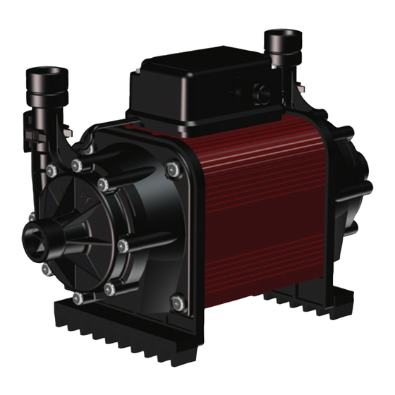
Shower pumps
Hide thumbs
Also See for SSL Series:
- Installation and operating instructions manual (17 pages) ,
- Installation and operating instructions manual (16 pages)


Need help?
Do you have a question about the SSL Series and is the answer not in the manual?
Questions and answers