Table of Contents
Advertisement
Leister Technologies AG
© 2013 Leister Technologies AG, CH-6056 Kaegiswil
Leister Technologies AG, Schwarzenbergstrasse 10, CH-6056 Kaegiswil/Switzerland
Tel. +41 41 662 74 74 Fax +41 41 662 74 16
www.leister.com
leister@leister.com
Operating Manual
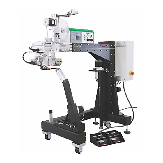
Welding Machine SEAMTEK 36
OPERATING MANUAL
Software-Version from V 3
Production Code 140528xxxx
SEAMTEK 36
Revision: A
1
QM
Page
1 / 62
Created
04.04.2014 TEX
Released
Modified
Advertisement
Table of Contents

Subscribe to Our Youtube Channel
Related Manuals for Leister SEAMTEK 36


Summary of Contents for Leister SEAMTEK 36
- Page 1 Modified OPERATING MANUAL Software-Version from V 3 Production Code 140528xxxx SEAMTEK 36 © 2013 Leister Technologies AG, CH-6056 Kaegiswil Leister Technologies AG, Schwarzenbergstrasse 10, CH-6056 Kaegiswil/Switzerland Tel. +41 41 662 74 74 Fax +41 41 662 74 16 www.leister.com leister@leister.com...
-
Page 2: Table Of Contents
Abbreviations __________________________________________________________________ 5 Disposal _______________________________________________________________________ 5 Introduction ______________________________________________________________ 6 Manual Conventions ________________________________________________________ 6 Manual Arrangement _______________________________________________________ 8 The SEAMTEK 36 ___________________________________________________________ 8 Operating Principle ________________________________________________________ 9 SP Specifications __________________________________________________________ 10 Technical Support _________________________________________________________ 10 Machine Physical Components ______________________________________________ 10 Base Frame ______________________________________________________________ 10 Primary Power Panel ______________________________________________________ 10 2.2.1 Graphite Vane Air Pump ____________________________________________________ 11... - Page 3 Operating Manual Page 3 / 62 Welding Machine SEAMTEK 36 Created 04.04.2014 TEX Leister Technologies AG Released Revision: A Modified A Word about Physical Environment __________________________________________ 19 Setup Procedure __________________________________________________________ 19 Pre-start Checklist ________________________________________________________ 19 Power and Air Requirements ________________________________________________ 20 3.4.1...
- Page 4 Operating Manual Page 4 / 62 Welding Machine SEAMTEK 36 Created 04.04.2014 TEX Leister Technologies AG Released Revision: A Modified 7.6.1 Upper Left Row—Seam Heat Correction _____________________________________ 44 7.6.2 Upper Left—Hands- Free Freewheel ________________________________________ 44 7.6.3 Upper- Right—Fabric Registration Error Correction ____________________________ 45 Calibration ______________________________________________________________ 45 7.8 Top Wheel Differential % _____________________________________________________ 46...
-
Page 5: Abbreviations
Operating Manual Page 5 / 62 Welding Machine SEAMTEK 36 Created 04.04.2014 TEX Leister Technologies AG Released Revision: A Modified (Translation of the original operating instructions) Abbreviations AHAM Articulating Hot Air Module Lower Wheel Module Quick Arm Side Arm Tape Delivery System... -
Page 6: Introduction
SEAMTEK 36. A troubleshooting checklist, warranty information, and an index are also included in this documentation. This manual is designed to ensure proper setup, installation, and operation of the SEAMTEK 36 with a minimum of effort. Please read through all sections of this document before using your SEAMTEK 36. - Page 7 Operating Manual Page 7 / 62 Welding Machine SEAMTEK 36 Created 04.04.2014 TEX Leister Technologies AG Released Revision: A Modified Warning: Symbols, like this one, alert you to practices that may cause damage to the machine. Opening the device is extremely dangerous, since live parts and connections are exposed.
-
Page 8: Manual Arrangement
10. Index 1.3 The SEAMTEK 36 Thank you for purchasing the world's finest rotary hot air welder. The SEAMTEK 36 is a computer-controlled hot air welder used for sealing industrial coated fabrics such as polyvinylchloride (PVC), polyurethane (PU), polyethylene (PE), and polypropylene (PP), which are used today for a vast array of important and interesting products. -
Page 9: Operating Principle
1.4 Operating Principle In operation, the SEAMTEK 36 directs a stream of hot air (from 200 to 1300 ° F, 35°C - 700°C) onto the joining surfaces of the coated fabric pattern pieces, which then roll between two drive... -
Page 10: Sp Specifications
Power: 230V~ to 240 V~, 50/60 Hz, single phase, 17 amps Weight: 330k The SEAMTEK 36 is a very precise machine in that it can maintain an air stream weld temperature within +/-2 degrees F (°C) and can maintain the speed of each drive wheel independently within +/- .01 inch per second at weld speeds ranging from 0.8 to 72’/min (0.25... -
Page 11: Graphite Vane Air Pump
Also located on the door the primary power panel is the service disconnect breaker, which is used to energize and de-energize the SEAMTEK 36. On the operator side of the Primary Power Panel is an Emergency Stop button. Pushing this button will instantly shut off all power and release all compressed air form the machine. -
Page 12: Upper Wheel Module
Operating Manual Page 12 / 62 Welding Machine SEAMTEK 36 Created 04.04.2014 TEX Leister Technologies AG Released Revision: A Modified depending upon what “button” is pushed. This is the control for adjusting temperature, speed, and other operation parameters. Caution: the operators’ fingers should only touch the touch screen. Sharp objects such as pencils and long fingernails can damage the touch screen. -
Page 13: Hot Air Module
There are 3 different lower wheel modules (LWM) that can be installed on any SEAMTEK 36 hot air welder. These are the Pedestal, Side Arm and Quick Arm. A SEAMTEK 36 can have just one or all 3 making the SEAMTEK 36 highly versatile. Each of these LWMs are independently driven by their own computer controlled stepper motors. - Page 14 Operating Manual Page 14 / 62 Welding Machine SEAMTEK 36 Created 04.04.2014 TEX Leister Technologies AG Released Revision: A Modified Pedestal Figure 3 Pedestal Ready to use Figure 4 Pedestal with the wide head...
-
Page 15: Side Arm Lower Wheel Module
Operating Manual Page 15 / 62 Welding Machine SEAMTEK 36 Created 04.04.2014 TEX Leister Technologies AG Released Revision: A Modified 2.7.2 Side Arm Lower Wheel Module The Side Arm lower wheel module provides the ability to weld tubular items to other fabric pieces. - Page 16 Operating Manual Page 16 / 62 Welding Machine SEAMTEK 36 Created 04.04.2014 TEX Leister Technologies AG Released Revision: A Modified Figure 6 Quick Arm LWM. Off to the right you can see the Side Arm in its stowed position. Figure 7 A tube being formed on the Quick Arm...
-
Page 17: Accessories
Released Revision: A Modified 2.8 Accessories The SEAMTEK 36 is capable of utilizing other attachments and accessories to make it even more flexible take a look at the following for more information. 2.8.1 Tape Delivery System The optional Tape Delivery System (TDS) module is designed to supply a steady stream of coated fabric tape or heat activated adhesive seam tape to the weld head area. -
Page 18: Wheels And Nozzles
Figure 9 Adjustable Tape Guide 2.8.2 Wheels and Nozzles The SEAMTEK 36 creates various seam widths and types using the wide variety of quick- change wheels and nozzles. Take a look at the options below. Steel Wheels 0.250” – 2.5” wide (8mm to 63.5mm) Silicone wheels 0.50”- 2.5”... -
Page 19: A Word About Physical Environment
3.2 Setup Procedure The SEAMTEK 36 is easy to set up. You should have a forklift on hand to off-load the crated machine from the shipper. When you have decided on a working location for your SEAMTEK 36, follow these steps: 1. -
Page 20: Power And Air Requirements
L1 (115v~) /L2 (115v~) / P.E. (ground) USA 3.4.2 Connecting Shop Air The SEAMTEK 36 requires clean dry air. Check to make sure that your air compressor system can provide the required air indicated on the “Rating Label”. Basic ratings: 100-120 psi / 690- 827 kpa @1cfm / 2.03 Kg/h... -
Page 21: Controls: Switches, Foot Pedals And Touch Screen
Released Revision: A Modified 4) Now you are ready to turn on the SEAMTEK 36. See section 5.0 on energizing (turning on) the SEAMTEK 36 for the first time. Figure 10 Shop air regulator disconnect plug 4.0 Controls: Switches, Foot Pedals and Touch Screen This section introduces you to the various switches, foot pedals, touch screen that you use to control the weld setup and welding process. - Page 22 Operating Manual Page 22 / 62 Welding Machine SEAMTEK 36 Created 04.04.2014 TEX Leister Technologies AG Released Revision: A Modified Figure 11 Main Control Screen Temperature Set point – This is the button that the operator presses to adjust the hot air temperature.
- Page 23 Operating Manual Page 23 / 62 Welding Machine SEAMTEK 36 Created 04.04.2014 TEX Leister Technologies AG Released Revision: A Modified Figure 12 Temperature set-up Keypad The operator then enters the desired set point and the presses the enter button in the lower left hand corner of the screen.
- Page 24 Operating Manual Page 24 / 62 Welding Machine SEAMTEK 36 Created 04.04.2014 TEX Leister Technologies AG Released Revision: A Modified Here’s a hint…Most of your PVC fabrics between 13 – 24 ounce (370 – 680 gsm) would require a setting of approximately 0.5 – 0.7 seconds. This also depends upon your temperature and speed setting but this is at least a good place to start testing from.
- Page 25 This is where the wheel diameters can be changed. Pulley count added – driver speed added. Stepper motor PPR must remain at 2000. 13. Test Mode- Leister Technologies AG has designed a function called the test mode to help the operator determine the perfect speed for a set temperature. See section 7.4...
-
Page 26: Air Cylinder Mode Select Switches
Operating Manual Page 26 / 62 Welding Machine SEAMTEK 36 Created 04.04.2014 TEX Leister Technologies AG Released Revision: A Modified 4.1.1 Air Cylinder Mode Select Switches Figure 14 Cylinder Switches These toggle switches control the air cylinders that move the Hot Air Module and Upper Wheel Module. -
Page 27: Wheel Pressure Regulators
Operating Manual Page 27 / 62 Welding Machine SEAMTEK 36 Created 04.04.2014 TEX Leister Technologies AG Released Revision: A Modified 4.1.2 Wheel Pressure Regulators Figure 15 Wheel Pressure Regulators These two regulators allow you to adjust wheel pressure. There are two adjustments you can make here: CLAMP PRESSURE and WELD PRESSURE. -
Page 28: Emergency Stop Button
Operating Manual Page 28 / 62 Welding Machine SEAMTEK 36 Created 04.04.2014 TEX Leister Technologies AG Released Revision: A Modified 4.2 Emergency Stop Button Figure 16 Emergency Stop Button To the right of the operators’ position on the power module is the red, EMERGENCY STOP button. -
Page 29: Lower Row - Motor And Cylinder Control
Operating Manual Page 29 / 62 Welding Machine SEAMTEK 36 Created 04.04.2014 TEX Leister Technologies AG Released Revision: A Modified Here’s a closer look at the six different foot pedal switches and their various functions: 4.3.1 Lower Row - Motor and cylinder control The lower rows of foot pedal switches are used to start and stop the drive wheel motors and to raise and lower the upper wheel module. -
Page 30: Energizing And De-Energizing
Perform the following steps: 1. Before you energize the SEAMTEK 36, verify that all three cylinder mode select switches are in the AUTO position. The cylinder mode select switches are WELD PRESSURE, CLAMP PRESSURE AND NOZZLE. -
Page 31: De-Energizing
Revision: A Modified 5.2 De-energizing When you are finished welding for the day, you will need to de-energize the SEAMTEK 36. It's a good idea to familiarize yourself with this process before you begin welding. To de-energize, follow these steps: 1. -
Page 32: Setting Weld Pressure And Clamp Pressure For The Upper Wheel Module
Operating Manual Page 32 / 62 Welding Machine SEAMTEK 36 Created 04.04.2014 TEX Leister Technologies AG Released Revision: A Modified 6.1 Setting Weld Pressure and Clamp Pressure for the Upper Wheel Module You must set weld pressure and clamp pressure before you begin welding. The initial settings you use are only starting points that you will begin with. - Page 33 Operating Manual Page 33 / 62 Welding Machine SEAMTEK 36 Created 04.04.2014 TEX Leister Technologies AG Released Revision: A Modified To do this, follow these steps: 1. To start the weld air pump, push the Air On button on the Status Screen. This activates the rotary vane pump.
-
Page 34: Setting Pre-Weld Starting Values
They will remain until you re adjust them. Note: Pre-weld settings can only be adjusted while the SEAMTEK 36 is in either the “Idle” or “Pause” state (not welding). This information is visible at all times on the Status Screen Let’s look at each of these pre-weld settings:... -
Page 35: Operations
Remember, these are only starting values to which all subsequent changes will be referenced. 7.0 Operations This section describes the operation of the SEAMTEK 36. Here you will learn how to place the fabric in the weld head, weld a test strip, and weld a typical seam. Foot pedal corrections and other in-operation adjustments are also covered in this section. -
Page 36: Welding Machine Seamtek
Operating Manual Page 36 / 62 Welding Machine SEAMTEK 36 Created 04.04.2014 TEX Leister Technologies AG Released Revision: A Modified The drive wheels disengage as long as the foot switch is held down, allowing you to pull the fabric panels into position. - Page 37 Operating Manual Page 37 / 62 Welding Machine SEAMTEK 36 Created 04.04.2014 TEX Leister Technologies AG Released Revision: A Modified Figure 20 Welding window There are a few other factors that come into play as well like pressure, and airflow. All of these will be covered in this section.
- Page 38 Operating Manual Page 38 / 62 Welding Machine SEAMTEK 36 Created 04.04.2014 TEX Leister Technologies AG Released Revision: A Modified When the operator pushes the test button the screen will change to look like this: Figure 21 Test Screen Description of buttons: Coarse Test mode - By default the machine starts in Coarse Test Strip mode.
- Page 39 Operating Manual Page 39 / 62 Welding Machine SEAMTEK 36 Created 04.04.2014 TEX Leister Technologies AG Released Revision: A Modified 2. Next, prepare some long strips of fabric about two inches (50mm) wide by at least 24 inches (61cm) long. Place the strips in the weld head as described in Placing Fabric in the Weld Head.
- Page 40 Operating Manual Page 40 / 62 Welding Machine SEAMTEK 36 Created 04.04.2014 TEX Leister Technologies AG Released Revision: A Modified Note: PVC welds quickly as it cools, but some fabric coatings such as polyurethane may take several minutes to cool and may actually increase in weld strength for several hours after being welded.
- Page 41 Operating Manual Page 41 / 62 Welding Machine SEAMTEK 36 Created 04.04.2014 TEX Leister Technologies AG Released Revision: A Modified Airflow – Airflow is a measurement of the amount of air that comes out of the nozzle. The airflow meter looks like this:...
-
Page 42: Welding A Typical Seam
Operating Manual Page 42 / 62 Welding Machine SEAMTEK 36 Created 04.04.2014 TEX Leister Technologies AG Released Revision: A Modified Figure 24 Fabric angle 7.4 Welding a Typical Seam Using one or both of the two test strip modes, you have determined the correct temperature and wheel speed combination. -
Page 43: Stopping And Starting On A Seam
The drive wheels stop and the upper wheel raises. The computer displays “Idle,” and the SEAMTEK 36 returns to clamp pressure when you take your foot off the pedal. The seam position indicator resets to zero when you start welding again. Remember you can use either foot pedal switch to stop the welding process. -
Page 44: Using The Foot Pedals
Note: Each closure of the BOTH + and BOTH - foot pedal switches is recorded as to where it occurred on the seam to an accuracy of 1/10 inch (2.5mm). If the SEAMTEK 36 is then placed in Repeat mode for the next seam, all foot pedal corrections from the previous seam will automatically be imposed. -
Page 45: Upper- Right-Fabric Registration Error Correction
Revision: A Modified fabric position between the wheels. You can access this feature only while the SEAMTEK 36 is in the "Pause" or "Idle" state, which means the drive wheels are not moving. See Placing Fabric in the Weld Head. -
Page 46: Top Wheel Differential
Operating Manual Page 46 / 62 Welding Machine SEAMTEK 36 Created 04.04.2014 TEX Leister Technologies AG Released Revision: A Modified Figure 25 Calibration This is the Calibration Screen. This is where the operator adjusts the effective diameter of each drive wheel. This is necessary whenever you change wheels to a different diameter or a different tread. -
Page 47: Basic Hot Air Welding
To do this, place the nozzle mode switch in the OUT position. This prevents the nozzle form entering the weld area but all other SEAMTEK 36 functions operate normally. -
Page 48: Be Ready To Stop
9.0 Changing Over Modular Features This section describes the steps necessary to change over and adjust the SEAMTEK 36’s modular features. Here you will learn how to remove, reconfigure all lower wheel modules and change wheel assemblies. -
Page 49: Pedestal
Operating Manual Page 49 / 62 Welding Machine SEAMTEK 36 Created 04.04.2014 TEX Leister Technologies AG Released Revision: A Modified 9.1.1 Pedestal Figure 26 Pedestal in storage position Figure 27 Pedestal in the welding position Gently pull the Pedestal up and back towards the operator. The kickstand will fall into the locking position as shown below. -
Page 50: Side Arm
Operating Manual Page 50 / 62 Welding Machine SEAMTEK 36 Created 04.04.2014 TEX Leister Technologies AG Released Revision: A Modified The kickstand locks the pedestal into the welding position 9.1.2 Side Arm Figure 29 Side arm in the welding position Figure 30 Side Arm in storage position To put the Side Arm into the welding position lift it until it is totally horizontally. -
Page 51: Quick Arm
Operating Manual Page 51 / 62 Welding Machine SEAMTEK 36 Created 04.04.2014 TEX Leister Technologies AG Released Revision: A Modified The kip handles thread into these locations. After the handles are tight you can reposition them by pulling out and rotating them. -
Page 52: Changing Wheel Assemblies
Operating Manual Page 52 / 62 Welding Machine SEAMTEK 36 Created 04.04.2014 TEX Leister Technologies AG Released Revision: A Modified Figure 34 Kip handle installed 9.2 Changing Wheel Assemblies The following procedures apply to wheel width/type changes for all wheel modules. -
Page 53: Upper Wheel Module, Wheel Assembly Removal And Change Over
Operating Manual Page 53 / 62 Welding Machine SEAMTEK 36 Created 04.04.2014 TEX Leister Technologies AG Released Revision: A Modified 9.2.1 Upper Wheel Module, Wheel Assembly Removal and Change Over The following sequence of pictures will assist you in changing the wheel for the Upper Wheel Module. -
Page 54: Pedestal, Wheel Assembly Removal And Change Over
Operating Manual Page 54 / 62 Welding Machine SEAMTEK 36 Created 04.04.2014 TEX Leister Technologies AG Released Revision: A Modified 9.2.2 Pedestal, Wheel Assembly Removal and Change Over After the screws With a 3/32 are loose slide Allen head the cover plates... - Page 55 Operating Manual Page 55 / 62 Welding Machine SEAMTEK 36 Created 04.04.2014 TEX Leister Technologies AG Released Revision: A Modified Figure 39 cover removed Figure 40 Belt tensioning device Figure 41 Wheel removed...
- Page 56 Operating Manual Page 56 / 62 Welding Machine SEAMTEK 36 Created 04.04.2014 TEX Leister Technologies AG Released Revision: A Modified Figure 42 Change the wheel Figure 43 Reverse the procedure to install the next wheel...
-
Page 57: Side-Arm, Wheel Assembly Removal And Change Over
Operating Manual Page 57 / 62 Welding Machine SEAMTEK 36 Created 04.04.2014 TEX Leister Technologies AG Released Revision: A Modified Figure 44 Install the side plate fasteners and mount the Pedestal head on the Pedestal body. Re-install the covers and you are ready to weld. - Page 58 Operating Manual Page 58 / 62 Welding Machine SEAMTEK 36 Created 04.04.2014 TEX Leister Technologies AG Released Revision: A Modified Using a 1/8’’ Allen head wrench, remove these 2 screws After the screws are removed the shoe back can be removed to release the wheel...
-
Page 59: Changing Nozzles
Operating Manual Page 59 / 62 Welding Machine SEAMTEK 36 Created 04.04.2014 TEX Leister Technologies AG Released Revision: A Modified 9.3 Changing Nozzles Nozzles are very simple to change Turn off the hot air and allow the nozzle to cool. -
Page 60: Adjusting Nozzle Position
Operating Manual Page 60 / 62 Welding Machine SEAMTEK 36 Created 04.04.2014 TEX Leister Technologies AG Released Revision: A Modified 9.3.1 Adjusting Nozzle Position This knob moves the nozzle closer or further away from the wheels This knob raises and lowers the nozzle in relation to the wheels. - Page 61 Operating Manual Page 61 / 62 Welding Machine SEAMTEK 36 Created 04.04.2014 TEX Leister Technologies AG Released Revision: A Modified Figure 51 Tape Delivery System...
- Page 62 Operating Manual Page 62 / 62 Welding Machine SEAMTEK 36 Created 04.04.2014 TEX Leister Technologies AG Released Revision: A Modified Upper Wheel Module side plates Adjustment Knob Slides Dowel Bolt Nylon Washer Delrin Roller Tensioner base plate Tape guide plates...
Need help?
Do you have a question about the SEAMTEK 36 and is the answer not in the manual?
Questions and answers