
Related Manuals for Feig Electronic TST WUI


Summary of Contents for Feig Electronic TST WUI
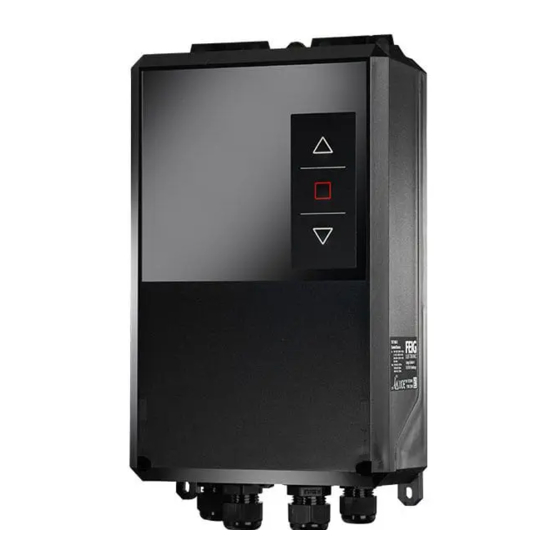
- Page 1 STARTUP TST WUI Important ! You must read the function description before operating, connecting or starting up door controller. preliminary public (B) 2005-09-07 WUI_Inbetriebnahme2_GB.doc...
- Page 2 The entity which has placed the TST WUI controller in service is solely responsible for the completeness of the startup manual. This Manual shows only a small range of the controller functions. Further functions and descriptions for individual door functions as well as more exact specifications for the controller and hazard notes can be found in the main description.
-
Page 3: Table Of Contents
Limit switch connection ......................10 Putting into operation Other connection possibilities Photo eye ............................12 External control device......................12 Inputs overview Outputs overview Outputs of TST WUI ........................13 Outputs of TST RWUI.........................13 General operating instructions for parameterisation Functions Messages overview 11.1 Error messages ..........................16 11.2... -
Page 4: Safety Information
It is forbidden to operate the contactors manually. If the protective foil is destroyed, the guarantee is void. FEIG ELECTRONIC GmbH Page 4 of 20 WUI_Inbetriebnahme2_GB.doc... -
Page 5: Technical Data
>17 V: active logical 1 Contact load capacity: ≥ 35 V / ≥ 200 mA If the safety chain is interrupted, no movement of the drive is possible, not even in deadman FEIG ELECTRONIC GmbH Page 5 of 20 WUI_Inbetriebnahme2_GB.doc... - Page 6 Protection class Protection class I Equipment type Motor appliance, external motor is not part of the delivery from FEIG ELECTRONIC GMBH Vibration low vibration installation, e.g. on a brick wall Protection class IP54 (IP65 by replacing CEE connection and sealing cable entries) All unused cable entries must be closed.
-
Page 7: Installation Of The Control System
The cable entries must not be subjected to any mechanical loads, especially tensile loads. Min. 100mm 50°C -10°C 3x400VAC, N, PE Min. 100mm Figure 3: Drilling plan Figure 2: Installation of the control system FEIG ELECTRONIC GmbH Page 7 of 20 WUI_Inbetriebnahme2_GB.doc... -
Page 8: Electrical Connection
21 22 CEE plug Fuse 5 pole, 16A, red 10 A / Type K IMPORTANT The mains plug must be visible and accessible from the control system. Figure 4: Mains cable connection FEIG ELECTRONIC GmbH Page 8 of 20 WUI_Inbetriebnahme2_GB.doc... -
Page 9: 3-Phase Motor Connection
Figure 5: 3-Phase Motor connection 4.3 1-Phase Motor connection X 28 K 200 - C lose K 200 - O pen -A 2 PE PE L3.1 21 22 230VAC M 1~ Fig. 6: 1-Phase motor connection FEIG ELECTRONIC GmbH Page 9 of 20 WUI_Inbetriebnahme2_GB.doc... -
Page 10: Safety Edge Connection
4.5 Limit switch connection thermopill Figure 8: Cam limit switch Figure 9: Cam limit switch connection IMPORTANT Check the electrical connection again before operating the control system. The appliance can be damaged by wrong connections. FEIG ELECTRONIC GmbH Page 10 of 20 WUI_Inbetriebnahme2_GB.doc... -
Page 11: Putting Into Operation
In order to avoid unintended operation of the barrier, only carry out the adjustment of the limit switches when EMERGENCY STOP is pressed or the control system is switched off ! 9. Barrier can now be operated in automatic mode. FEIG ELECTRONIC GmbH Page 11 of 20 WUI_Inbetriebnahme2_GB.doc... -
Page 12: Other Connection Possibilities
Startup Other connection possibilities 6.1 Photo eye 6.2 External control device Figure 10: Photo eye connection Figure 11: External control device Inputs overview 9 10 FEIG ELECTRONIC GmbH Page 12 of 20 WUI_Inbetriebnahme2_GB.doc... -
Page 13: Outputs Overview
Startup Outputs overview 8.1 Outputs of TST WUI L3.1 20 21 22 Rotating Magnet flashing light voltage Abbildung 12: Outputs TST WUI 8.2 Outputs of TST RWUI K5 K6 K9 K10 K11 K12 K13 K14 FEIG ELECTRONIC GmbH Page 13 of 20... -
Page 14: General Operating Instructions For Parameterisation
The last saved value is obtained Å ..automatically stopped immediately, gate operation is active again Reset the control system Å+ + press simultaneously and keep pressed for ca. 3 seconds. FEIG ELECTRONIC GmbH Page 14 of 20 WUI_Inbetriebnahme2_GB.doc... -
Page 15: Functions
• Ebcl → delete complete failure memory Eb - • Eb - → Cancel (Display noEr: no errors) Display the software version You will find more parameters and functions in the main handbook of the controller TST WUI FEIG ELECTRONIC GmbH Page 15 of 20 WUI_Inbetriebnahme2_GB.doc... -
Page 16: Messages Overview
Fault: Maintenance is required Service counter has expired F.080 Parameters not set • Controller not parameterized The basic parameters (P.205) for the TST WUI controller have not F.090 yet been set. Safety chain faults • Internal E-Stop „push-button“ E-Stop chain was interrupted starting at input „internal E-Stop“... - Page 17 • External watchdog incorrect Defective hardware or noise-saturated environment F.930 ROM error • Wrong EPROM code F.931 • Defective hardware or noise-saturated environment • RAM error Defective hardware or noise-saturated environment F.932 FEIG ELECTRONIC GmbH Page 17 of 20 WUI_Inbetriebnahme2_GB.doc...
- Page 18 Program version / New EPROM version F.964 manufacturer code • Controller not yet initialized Plausibility Param.block error • New EPROM version F.970 • Controller not yet initialized • Some parameter is implausible FEIG ELECTRONIC GmbH Page 18 of 20 WUI_Inbetriebnahme2_GB.doc...
-
Page 19: Information Messages
Input 1 E.101 Input 2 E.102 Input 3 E.103 Input 4 E.104 Input 5 E.105 Input 6 E.106 Input 7 E.107 Input 8 E.108 Input 9 E.109 Input 10 E.110 Safety/Emergency stop chain FEIG ELECTRONIC GmbH Page 19 of 20 WUI_Inbetriebnahme2_GB.doc... - Page 20 External safety edge activated but not yet plugged in E.379 RC plug-in module RC Channel 1 E.401 RC Channel 2 E.402 Induction loop processor plug-in module Detector Channel 1 E.501 Detector Channel 2 E.502 FEIG ELECTRONIC GmbH Page 20 of 20 WUI_Inbetriebnahme2_GB.doc...
Need help?
Do you have a question about the TST WUI and is the answer not in the manual?
Questions and answers