
Related Manuals for Feig Electronic cVEND plug


Summary of Contents for Feig Electronic cVEND plug
- Page 1 INSTALLATION cVEND plug Contactless Payment and Ticketing Module Preliminary Confidential plug - User manual.docx 2015-02-20 - cVEND...
- Page 2 FEIG ELECTRONIC call explicit attention that devices which are subject of this document are not designed with components and testing methods for a level of reliability suitable for use in or in connection with surgical implants or as critical components in any life support systems whose failure to perform can reasonably be expected to cause significant injury to a human.
-
Page 3: Table Of Contents
4.6. Wake-Up ........................... 16 4.7. Connector X6, X11, X12 - Extension Interfaces ............. 17 4.7.1. Connector X6 - RGB Display (cVEND plug flex only) ..........17 4.7.2. Connector X11 - SAM and SD Interface ..............18 4.7.3. Connector X12 - Auxiliary Interfaces ................18 5. -
Page 4: Warnings - Read Before Start-Up
The security circuit will be triggered if security relevant parts are disassembled. In such cases the device stops regular operation and can be reactivated only by the manufacturer in a certified secure environment. FEIG ELECTRONIC GmbH Page 4 of 24 cVEND plug - User manual.docx... -
Page 5: Characterization
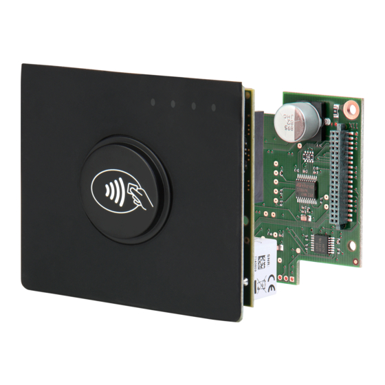
Installation cVEND plug 2. Characterization The cVEND plug is a secure contactless module for contactless credit cards (open-loop) and public transport tickets (closed-loop). It fulfills the newest functional and security related payment card industry standards. cVEND plug is designed for flush integration into non conducting housings. It is EMVCo contact- less certified, if installed according the guidelines described in this manual. - Page 6 Installation cVEND plug Fig. 1: cVEND plug front view - not installed Fig. 2: cVEND plug rear view - not installed Table 1: Interfaces and connectors Label Description LEDs (4 x green, 1 x yellow, 1 x red) From outside visible, illuminated plastic dome “Plug”...
-
Page 7: Mechanical Integration
The contactless logo must be visible. The upper edge of the cVEND plug plastic dome and the target terminal front plate must be on the same level. Avoid any kind of conducting material surrounding the cVEND plug. - Page 8 Installation cVEND plug The cVEND plug front consists of a silicon rubber mat (1) with integrated sealing (2) and a fixed poly carbonate plastic dome (3) which shows the back-lit contactless symbol. Fig. 4: Plug front with sealing (red colored) For fastening the cVEND plug front has to be pressed tight against the housing front.
-
Page 9: Dimensions
Installation cVEND plug 3.1. Dimensions Fig. 6: cVEND plug front with LED position Fig. 7: cVEND plug rear and side view (without cVEND SAM Extension Board) FEIG ELECTRONIC GmbH Page 9 of 24 cVEND plug - User manual.docx... -
Page 10: Connection
Installation cVEND plug 4. Connection The connector I/O PINs are described from the cVEND plug view. A cVEND plug input must be connected to one output or vice versa. 1 2 3 4 5 6 6 5 4 3 2 1 Fig. -
Page 11: Connector X1 - Ethernet Interface
CAT 5 cables are recommended to ensure a reliable operation at 10 Mbps or 100 Mbps. Fig. 10: Ethernet Interface at connector X1 Required Connector: RJ45 Table 2: Pin Assignment Ethernet Connector Label VETH+ VETH+ VETH- VETH- FEIG ELECTRONIC GmbH Page 11 of 24 cVEND plug - User manual.docx... -
Page 12: Connector X2 - Usb Device Interface
Crimp contact, Female, grid dimension 3.0 mm, AWG#20-24, Molex Micro Fit Table 3: Pin Assignment USB Connector Label Direction DEV-Vcc DEV-D- DEV-D+ N.C. Shield NOTE: The USB interface is specified for max. 5 m (16,4 ft) cable length. FEIG ELECTRONIC GmbH Page 12 of 24 cVEND plug - User manual.docx... -
Page 13: Connector X3 - Rs232 V.24 (Uart#1) Interface
Crimp contact, Female, grid dimension 3.0 mm, AWG#20-24, Molex Micro Fit Table 4: Pin Assignment RS232 V.24 Interface Label Direction Remark Device TXD Device RXD Wake-UP see 4.6. Wake-Up FEIG ELECTRONIC GmbH Page 13 of 24 cVEND plug - User manual.docx... -
Page 14: Connector X4 - Rs232-Lvttl (Uart#0) Interface
4.6. Wake-Up NOTE: The length of the cable to the RS232-LVTTL interface should be kept as short as possible, and must in any case not exceed 3 m. FEIG ELECTRONIC GmbH Page 14 of 24 cVEND plug - User manual.docx... -
Page 15: Connector X5 - Power Supply Vcc
IEC EN 60950-1 chapter 2.5, only. Reversing the polarity of the supply voltage may destroy the device. Supply voltages outside the specifications may destroy the device. FEIG ELECTRONIC GmbH Page 15 of 24 cVEND plug - User manual.docx... -
Page 16: Wake-Up
Fig. 15: cVEND internal Wake-up circuit NOTE: If the standby - wakeup option is used in connection with the USB interface the USB con- nection will be interrupted while standby mode. FEIG ELECTRONIC GmbH Page 16 of 24 cVEND plug - User manual.docx... -
Page 17: Connector X6, X11, X12 - Extension Interfaces
Some of the Extension Interfaces may need a dedicated software driver which may not pro- vided by the standard cVEND SDK. 4.7.1. Connector X6 - RGB Display (cVEND plug flex only) X6 is intended for connecting an external custom specific RGB Display. technical details are avail- able on request. -
Page 18: Connector X11 - Sam And Sd Interface
Installation cVEND plug 4.7.2. Connector X11 - SAM and SD Interface Fig. 17: cVEND plug X11 - PIN assignment. 4.7.3. Connector X12 - Auxiliary Interfaces Fig. 18: cVEND plug X12 - PIN assignment. FEIG ELECTRONIC GmbH Page 18 of 24... -
Page 19: Technical Data
Battery 3V Lithium Battery, 540 mAh, Lifetime 10 year at 25 °C Battery is needed for security function and RTC. Higher temperature will reduced lifetime! FEIG ELECTRONIC GmbH Page 19 of 24 cVEND plug - User manual.docx... -
Page 20: Standard Compliance
When properly used this radio equipment conforms to the essential requirements of Article 3 and the other relevant provisions of the R&TTE Directive 1999/5/EC of March 99. Performance Classification according to ETSI EN 301 489: Class 2 FEIG ELECTRONIC GmbH Page 20 of 24 cVEND plug - User manual.docx... -
Page 21: Usa (Fcc) And Canada (Ic)
Warning: Changes or modification made to this equipment not expressly approved by FEIG ELECTRONIC GmbH may void the FCC authorization to operate this equipment. Installation with FCC / IC Approval: FCC-/IC-NOTICE: To comply with FCC Part 15 Rules in the United States / with IC Radio Stand- ards in Canada, the system must be professionally installed to ensure compliance with the Part 15 certification / IC certification. - Page 22 Installation cVEND plug FEIG ELECTRONIC GmbH Page 22 of 24 cVEND plug - User manual.docx...
-
Page 23: Cvend Plug Sam Extension - Option
6. cVEND plug SAM Extension - Option The optional SAM Extension board offers 4 sockets for ID000 Format smart cards and one SDHC memory card socket. It can be connected to cVEND plug via connector X11 and X12. SAM3 SAM4... - Page 24 C interfaces as well as digital GPIOs are provided. NOTICE: Some interfaces may need a dedicated software driver which may not provided by the standard cVEND SDK. Fig. 21: cVEND plug SAM Extension - X20 Pin assignment microSD Socket Removal Memory SD Host Controller Version 2.0...
Need help?
Do you have a question about the cVEND plug and is the answer not in the manual?
Questions and answers