Table of Contents
Advertisement
Quick Links
Advertisement
Table of Contents

Related Manuals for Barco Thor series


Summary of Contents for Barco Thor series
- Page 1 Thor series Installation manual ENABLING BRIGHT OUTCOMES...
- Page 2 Barco NV President Kennedypark 35, 8500 Kortrijk, Belgium www.barco.com/en/support www.barco.com...
- Page 3 Changes Barco provides this manual 'as is' without warranty of any kind, either expressed or implied, including but not limited to the implied warranties or merchantability and fitness for a particular purpose. Barco may make improvements and/or changes to the product(s) and/or the program(s) described in this publication at any time without notice.
- Page 4 Barco. If the purchaser or a third party carries out modifications or repairs on goods delivered by Barco, or if the goods are handled incorrectly, in particular if the systems are operated incorrectly or if, after the transfer of risks, the goods are subject to influences not agreed upon in the contract, all guarantee claims of the purchaser will be rendered invalid.
-
Page 5: Table Of Contents
Connecting the projector with the mains electricity .......................55 Power loop through to the projector electronics ......................56 6.10 Connecting a UPS to the projector electronics ........................57 6.11 Installing the Communicator Touch Panel .........................58 7 Lenses & Lens selection...................................61 R5906788-03 Thor series... - Page 6 9.16 Installing a HDD into the ICMP............................... 103 10 Starting up........................................105 10.1 Switching the Thor series projector ON..........................106 10.2 Switching the Thor series projector OFF .......................... 107 10.3 Projector ON/OFF cycle explained ............................108 11 Scheimpflug ........................................111 11.1 Scheimpflug introduction ................................112 11.2 Scheimpflug adjustment ................................113...
- Page 7 Specifications of the Thor................................154 Specifications of the Thor+............................... 155 Specifications of the ICMP ............................... 156 Dimensions of the Thor series projector ........................... 158 Technical Regulations ................................. 159 B Pin configurations...................................... 161 About General Purpose Inputs & Outputs (GPIO) ...................... 162 Pin configurations of the Cinema Controller communication ports..............
- Page 8 R5906788-03 Thor series...
-
Page 9: Welcome
Congratulations May we congratulate you on your purchase of a Barco Thor! It is our sincere wish that this digital projector meets up to your every expectation and that you thereby take a little time to page through this important manual. -
Page 10: About This Manual
Some illustrations and descriptions in this document may be different than the product delivered. E. g. Illustrations with two chillers instead of one. For Thor series only one chiller has to be taken into account. -
Page 11: Safety Information
“warnings” and “cautions” are given depending on the procedure. Read and follow these “warnings” and “cautions” as well. Clarification of the term “Thor series” used in this document When referring in this document to the term “Thor series” means that the content is applicable for following Barco products: •... -
Page 12: General Considerations
Owner's record The part number and serial number are printed on a label which is stuck on the respective part. Record these numbers in the spaces provided below. Refer to them whenever you call upon your Barco dealer regarding this product. -
Page 13: Important Safety Instructions
6mm , 10AWG to 8AWG. The electrical rating of the Thor+ projector is 200-240V/346-415V 3W+N+PE 16A 50-60Hz (Y connection) (Y connection). The electrical rating of the Thor projector is 200-240V/346-415V 3W+N+PE 10A 50-60Hz (Y connection) (Y connection). R5906788-03 Thor series... - Page 14 Do not place flammable or combustible materials near the projector! • Barco large screen projection products are designed and manufactured to meet the most stringent safety regulations. This projector radiates heat on its external surfaces and from ventilation ducts during normal operation, which is both normal and safe.
- Page 15 Never use water on an electrical fire. Always have service performed on this projector by authorized Barco service personnel. Always insist on genuine Barco replacement parts. Never use non-Barco replacement parts as they may degrade the safety of this projector.
- Page 16 Replacement parts: When replacement parts are required, be sure the service technician has used original Barco replacement parts or authorized replacement parts which have the same characteristics as the Barco original part. Unauthorized substitutions may result in degraded performance and reliability, fire, electric shock or other hazards.
-
Page 17: Product Safety Labels
Therefore a liquid cooling system is provided consisting of liquid circuits inside the projector which are connected via hoses to external chillers. Only chiller models and hoses exclusively developed for this application and approved by Barco are allowed to be used. Barco approved chillers models are listed on the Barco website. - Page 18 DIRECTE DES YEUX AU FAISCEAU RG3 IEC EN 62471-5:2015 CLASS 1 IEC EN 60825- 1:2014 DISTANCE DE SECURITE : CONSULTER LE MANUEL DE SECURITE Beam stop. Arrêt de faisceau. 光束衰减器 Enable key. Clé de active. 启动钥匙 Hazard RG3: not for household use symbol R5906788-03 Thor series...
-
Page 19: High Brightness Precautions: Hazard Distance (Hd)
To protect untrained end users (as cinema visitors, spectators) the installation shall comply with the following installation requirements: Operators shall control access to the beam within the hazard distance or install the product at the height that will prevent spectators' eyes from being in the hazard distance. Radiation levels in R5906788-03 Thor series... - Page 20 (RZ) in the theater must be established. This can be done by using physical barrier, like a red rope as illustrated in Image 2-2. The restricted area sticker can be replaced by a sticker with only the symbol. R5906788-03 Thor series...
- Page 21 • This product can only be installed by Barco or sold or leased only to valid laser light show variance holders. In other words our installers are required to have an approved laser light show variance. Such installers may currently hold a valid variance for production of Class IIIb and IV laser light shows and/or for incorporation of the RG3 LIPs into their shows.
-
Page 22: Hd For Fully Enclosed Projection Systems
The light emitted from the screen within the observation shall never exceed the RG2 exposure limit, determined at 10 cm. The HD can be neglected if the measured light at the screen surface is below 5000 diffuse cd/m² or 15000 LUX. R5906788-03 Thor series... -
Page 23: Hd In Function Of Modifying Optics
THOR+ THOR 1 1,1 1,2 1,3 1,4 1,5 1,6 1,7 1,8 1,9 2 2,1 2,2 2,3 2,4 2,5 2,6 2,7 2,8 2,9 3 3,1 3,2 3,3 3,4 3,5 3,6 3,7 3,8 3,9 4 Throw Ratio Image 2-4 R5906788-03 Thor series... - Page 24 Safety Information R5906788-03 Thor series...
-
Page 25: System Overview
Note that the latest version of this document and all other related documentation sets are available on the Barco website. Different components of the projection system. - Page 26 System overview • Commander & Web Commander R5906788-03 Thor series...
-
Page 27: Thor
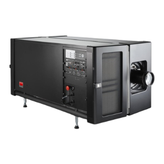
The Thor series projector is a RGB laser-illuminated projector. This high-brightness laser projector is capable of showing 4K content at 60 fps and 3D movies in full 4K resolution. The Thor series projector has an integrated color 3D system, with 6-Primary (6P) color laser modules. This Barco Laser3D system maximizes 3D efficiency from a single projector, delivering constant and uniform images in excellent contrast, without lamp flicker. -
Page 28: Chillers And Hoses
Projector ID label. Air flow The Thor series projector has two air flow channels (reference A & B) to cool the projector electronics. The air intake is at the front side of the projector, the air outlet is at the back side. - Page 29 Hoses Only hoses specified by Barco can be used to couple the cooling liquid of the chiller with the cooling circuit of the projector. The hoses specified are specially designed for this purpose. Using other hoses than those will...
-
Page 30: Safety System
DMD cooling. However, take into account that the couplings are of the same type and size. So, ensure to connect the right hose with the right cooling channel. See Barco website for available kits of hoses and corresponding ordering information. Image 3-7: Hose with 90° angle female coupling. -
Page 31: Communicator Touch Panel
- using an elegant and flexible Touch Panel interface. The interface's commonality means that operators can intuitively use any model in the product line, without restriction, and its user-friendly nature translates directly into a short and enjoyable learning curve. R5906788-03 Thor series... - Page 32 Flexible Touch Panel interface The Touch Panel interface can be mounted upon a swivel arm which easily fits on top of the Thor series. One central locking mechanism of the swivel arm allows instant fixation of the Touch Panel interface in any position.
-
Page 33: Communicator Pc Version
The enabled functions are only accessible via a password entry and that prevents misalignment once everything is correctly aligned. The Communicator PC version has its own user guide which latest version is available on the Barco website. -
Page 34: Commander & Web Commander
The ‘Barco Web Commander’ user interface is readily available on the projector without any additional software installation. It is accessed via a web browser and is also fully supported on iOS and Android tablets thanks to the free ‘Barco CineMate’ iOS and Android app. -
Page 35: Getting Started
Getting started About this chapter Read this chapter before installing your Thor series projector. It contains important information concerning installation requirements for the Thor series projector, such as minimum and maximum allowed ambient temperature, humidity conditions, required safety area around the installed projector, required power net, etc. -
Page 36: Installation Requirements
Therefore a liquid cooling system is provided consisting of liquid circuits inside the projector which are connected via hoses to external chillers. Only chiller models and hoses exclusively developed for this application and approved by Barco are allowed to be used. Barco approved chillers models are listed on the Barco website. - Page 37 Main Power requirements The Thor series projector operates from a nominal 3W+N+PE or 3W+PE power net. The projector must be switched internally between a star connection to a delta connection or vice versa. See installation instructions.
-
Page 38: Unpacking The Projector
The Thor series projector does not have a built in UPS unit. Projection screen The Thor series projector performs best when the image is projected on white screen with minimum gain (between 1 and 1.8). Very high gain screens (e.g. silver screens with gain 2.4) are not recommended. - Page 39 Note: The top side of the projector is foreseen with four threaded holes M10 (25 mm depth), one in each corner. These holes can be used to insert eyebolts to connect the shackles of the lifting equipment. R5906788-03 Thor series...
-
Page 40: Initial Inspection
This check should confirm that there are no broken knobs or connectors, that the cabinet and panel surfaces are free of dents and scratches, and that the operating panel is not scratched or cracked. The Barco Sales and Service office should be notified as soon as possible if this is not the case. -
Page 41: Installation Process
This chapter gives an overview of all the different stages in the installation process which you have to be followed to set your Thor series projector up and running. Each stage is briefly described and refers to more detailed step by step procedures in this manual. -
Page 42: Installation Process Overview
Note that a solid pedestal is required to support the projector. For more info see topic “Installation requirements”, page 36. Tip: Barco offers a pedestal for the Thor series series projector. This pedestal allows for a solid and easy setup of the projector and chillers that fit underneath the pedestal. - Page 43 SCOPE. See user guide of the Communicator. Backup of all projector configuration files. See user guide of the Communicator. Registration of the projector. The Thor series projector is DCI compliant and should be registered. Projection of a digital cinema movie.
- Page 44 Installation process R5906788-03 Thor series...
-
Page 45: Physical Installation
Physical installation About this chapter This chapter describes how the mechanical and electrical set up of your Thor series projector has to be done. Overview • Removing the transport protection bars • Positioning the projector at port window • Connecting the hoses with projector and chillers •... -
Page 46: Removing The Transport Protection Bars
6.2 Positioning the projector at port window General guidelines • Use a solid pedestal to mount the Thor series projector on to. Ensure that the pedestal can support the weight of the projector and that all feet of the projector are captured. •... - Page 47 Physical installation 20 cm Image 6-3: Positioning at port window Barco offers a pedestal for the Thor series series projector. This pedestal allows for a solid and easy setup of the projector and chillers that fit underneath the pedestal. Required tools •...
- Page 48 Later, when the projector is up-and-running, adjust precise image geometry and placement. Projector tilting In an ideal installation, the Thor series projector lens surface is centered with and parallel to the screen. This orientation helps to ensure optimized lens performance with minimal offset. If this position is not possible (such as when the projector is significantly higher than the center of the screen), it is better to rely on offset rather than extra tilt.
-
Page 49: Connecting The Hoses With Projector And Chillers
The length of the hoses depend on the position of the chillers in relation to the projector. The maximum length is 10 meter! Depending on the projector model one or two chillers are required! For the Thor series projector one chiller has to be installed. The Thor+ series needs two chillers. - Page 50 R/B IN R/B OUT The Thor series projector requires only one chiller. The circuits G-IN and G-OUT are omitted. How to connect the hoses? Ensure that all connectors of the hoses, chillers and projector are clean. Wipe away any dust before attaching.
-
Page 51: Connecting The Data Cable With Projector And Chillers
Next to connecting the hoses, the communication port of the chillers has to be connected with each other and with the projector. Depending on the projector model one or two chillers are required! For the Thor series projector one chiller has to be installed. The Thor+ series needs two chillers. - Page 52 Loosen the retaining screw (reference 3 Image 6-12) of the inner front door (door with the Stop button). Use a 3 mm Allen wrench. Pivot the inner front door to have full access the mains compartment parts. R5906788-03 Thor series...
-
Page 53: Connecting The External Safety Interlocks
The internal master key can be extended with a single pole external master key (MK). Insert the 10 pole terminal block back in its socket. Use a small screw driver to fixate the terminal block. Insert the cable(s) in the cable tie located below the terminal block (reference 5 Image 6-13). R5906788-03 Thor series... -
Page 54: Three Phase Power Input Configuration Of The Projector
The Υ/Δ configuration block is located inside the mains compartment. This procedure assumes that the cover of the mains compartment is already removed. See chapter “Accessing the mains compartment”, page 51. Required tools • Nut driver 10 mm R5906788-03 Thor series... -
Page 55: Connecting The Projector With The Mains Electricity
CAUTION: The cross-sectional area of the conductors in the AC power supply cord shall be not less than 4mm to 6mm , 10AWG to 8AWG in case of a star (Y) configuration and not less then , 8AWG in case of a delta (Δ) configuration. R5906788-03 Thor series... -
Page 56: Power Loop Through To The Projector Electronics
This procedure explains how to provide the projector electronics with power in case no UPS unit is used. Note that the projector is by default configured for use without UPS. So, the short power link cable is already installed. R5906788-03 Thor series... -
Page 57: Connecting A Ups To The Projector Electronics
Release the fixation spring. Image 6-18 6.10 Connecting a UPS to the projector electronics WARNING: Only use UPS units which are suitable for the Thor series series projector. See chapter “Installation requirements” for more information about the requirements of the UPS. Required tools No tools required. -
Page 58: Installing The Communicator Touch Panel
Image 6-21) upon the rod of the mounting plate, then add the lock washer (reference 2 Image 6-21), then fasten the mounting plate and the swivel arm together. When the arm is mounted, turn the nut (reference 1 Image 6-21) against the arm to secure the position. R5906788-03 Thor series... - Page 59 Place the Touch Panel interface upon the mounting plate of the swivel arm and fasten the two wing nuts (reference 5 Image 6-23) as illustrated. Image 6-23 Connect the DC plug, the RJ45 Ethernet plug and the D-SUB plug of the customized cable into their respective sockets on the Touch Panel interface. R5906788-03 Thor series...
- Page 60 (reference 7 Image 6-26), reposition the Touch Panel interface in the desired location, and fasten the swivel lock. Image 6-26 Caution: Never release the central swivel lock without supporting the Touch Panel interface. R5906788-03 Thor series...
-
Page 61: Lenses & Lens Selection
About this chapter This chapter gives an overview of available lenses for your Thor series and explains how to select the best suited lens for a specific situation using the lens calculator. Also, it is explained how to install and remove a lens from the projector Lens Holder and how to shift, zoom and focus the lens. -
Page 62: Available Lenses
Lenses & Lens selection 7.1 Available lenses Which lenses are available for my projector? The table below is subject to changes and was last updated on 22/12/2017. Consult Barco's web site for the most recent information about available lenses. Throw Range... -
Page 63: Lens Installation
7.3 Lens installation If no lens is installed the lasers of the Thor series series projector can not be powered. The Standby button en Light button will light up red. The Projector Toolset will also show the error message that there is no lens installed. - Page 64 Check if the lens is really secured by trying to pull the lens out of the Lens Holder. Activate the corresponding lens parameters for the installed lens. (See user guide of the “Projector Toolset” chapter Installation > Advanced > Lens parameters) R5906788-03 Thor series...
-
Page 65: Lens Removal
Lens to protect the optics of the Lens. It's recommended to place the plastic cover of the original projector packaging, back into the lens opening to prevent intrusion of dust. This plastic cover prevents that dust is entering the projector. R5906788-03 Thor series... -
Page 66: Lens Shift, Zoom & Focus
Lenses & Lens selection If no lens is installed the lasers of the Thor series series projector can not be powered. The Standby button en Light button will light up red. The Projector Toolset will also show the error message that there is no lens installed. - Page 67 PURPLE : When pushing the Shift, Zoom or Focus button the backlight color is purple of the part of the button that is pushed. This indicates that the requested action is ongoing. • RED : The backlight color of the Shift, Zoom and Focus buttons is red in case of end of range. R5906788-03 Thor series...
- Page 68 Lenses & Lens selection R5906788-03 Thor series...
-
Page 69: Input & Communication
This chapter describes the functionality of the Local Keypad, the projector Status Light (tail light) and the different input and communication ports of your Thor series projector. Note that all information about the ICMP is gathered into one separated chapter: “ICMP”, page 77. -
Page 70: Introduction
General The Input & Communication side of the Thor series projector consists of a Local Keypad integrated into the projector housing and a card cage with three slots. The rear side of the projector is equipped with a tail light which reflects the status of the projector. -
Page 71: Laser Status
8.3 Laser Status About the Laser Status Light The Laser Status Light is located at the rear top of the projector (reference 2 Image 8-3). The Laser Status Light is a real time indicator of the laser condition. R5906788-03 Thor series... -
Page 72: Local Keypad
Not safe to open the sealed compartments due to risk of cond dew point of the boot area is too high. Wait until the status light turns off and remains off. 8.4 Local Keypad Identification of the buttons FOCUS SHIFT ZOOM Image 8-4 R5906788-03 Thor series... - Page 73 The Dowser button (reference 8 Image 8-4) opens or closes the dowser. The backlight of the Dowser button is green when the dowser is requested to open and white when the dowser is closed. Red indicates an error. R5906788-03 Thor series...
-
Page 74: Cinema Controller
The Cinema Controller is equipped with a USB port, type “B” connector, (reference 2 Image 8-5) to connect upstream devices (E.g. PC). This USB port is used to communicate with the projector via RS232 commands (Virtual comport). The USB IN port remains operational in Standby mode. R5906788-03 Thor series... - Page 75 DHCP server. The Thor series can be connected to a WAN (Wide area network) (reference 6 Image 8-5). Once connected to the WAN, users can access the projector from any location, inside or outside (if allowed) their company network using the Communicator software.
- Page 76 The USB-IN port of the communication interface supports RS232 serial communication. You can use the RS232 input port to connect a local PC to your Thor series projector. This way you can configure and control your Thor series projector from your local PC via RS232 (serial) communication protocol.
-
Page 77: Icmp
ICMP HDMI 1.4 specifications • ICMP status LEDs • ICMP HDD status LEDs • ICMP device certificate • ICMP configuration via Communicator • ICMP reset • Obtaining the Barco ICMP certificate • Removing a HDD from the ICMP R5906788-03 Thor series... - Page 78 ICMP • Installing a HDD into the ICMP R5906788-03 Thor series...
-
Page 79: Icmp Introduction
As an integrated component of the projector, installation and maintenance of the ICMP requires the same skills and the same precautions as an intervention on the projector itself. For order info see www.barco.com. Front face of the ICMP The last produced model is equipped with two HDMI 2.0 as video source. -
Page 80: Icmp Hdd
The Card Cage can be different depending the projector type but it always consists of a button module and several removable units. The ICMP (reference 1) is inserted into the former ICP slot and IMB slot above the Barco Cinema Controller (reference 2). ICMP location in the Card Cage of a L-series projector. - Page 81 HDD models validated by Barco Only the original HDD spare parts provided by Barco or models validated by Barco (see list below) can be used in the ICMP. All deviations from this rule void warranty.
-
Page 82: Icmp Communication Ports
The ICMP can be connected to a USB 2.0 Media to load content. The USB port can be used to load content (DCP) or keys (KDM). NOTE: It is recommended to use the USB 3.0 ports for faster ingest. R5906788-03 Thor series... -
Page 83: Icmp Source Input Ports
The last produced model is equipped with two HDMI 2.0 (Reference 8, Image 9-8) as video source. Image 9-8: ICMP (with HDMI 2.0). Some models with DisplayPorts (Reference 11, Image 9-9) and HDMI 1.4 (Reference 10, Image 9-9) are still present on the field. Image 9-9: ICMP (with DisplayPort and HDMI 1.4). R5906788-03 Thor series... -
Page 84: Icmp Displayport Specifications
8 bpc, 10 bpc Single 1280 x 800 @ 60 fps 8 bpc, 10 bpc Single 1280 x 720 @ 60 fps 8 bpc, 10 bpc Single 1680 x 1050 @ 60 fps 8 bpc, 10 bpc Single R5906788-03 Thor series... - Page 85 DisplayPort A and DisplayPort B automatically detect: Active Pixels, and Active Lines Vertical Refresh 8 bits/color - 10 bits/color Frame locked • All input resolutions are scaled towards the desired resolution specified in the screen presentation file. • Fractional frame rates = (Hz*1000)/1001 R5906788-03 Thor series...
-
Page 86: Icmp Sdi Specifications
1080p 50/60 (Level A) 3Gb/s 1080p 4:4:4 (Level B) 3G HD-SDI uses a higher data rate (2.97 Gb/s). This allows a single cable interface to achieve the same capabilities of a Dual-Link HD-SDI implementation. Not supported in Alchemy R5906788-03 Thor series... - Page 87 1920 x 1080 23.976 23.976 Segmented frame SMPTE 428-9 2048 x 1080 Y Cb Cr 4:2:2 10-Bit (SMPTE RP211) 29.97 29.97 SMPTE 274M 1920 x 1080 Interlaced 29.970 59.940 Y Cb Cr 4:2:2 10-Bit Dual-Link HD-SDI (SMPTE 372M) formats R5906788-03 Thor series...
- Page 88 The Dual-Link HD-SDI interface can be used to carry a single 4:4:4 image, having a color depth of 10 or 12 bit per component. Both RGB (XYZ) and Y Cb Cr color spaces are supported. SMPTE 424M 3G HD-SDI 2.970 Gb/s SIGNALS 3G HD-SDI (SMPTE 425) formats mainly used to carry stereoscopic images. R5906788-03 Thor series...
-
Page 89: Icmp Hdmi 2.0 Specifications
Both HDMI 2.0 inputs are fully compliant with the HDMI 1.4, 1.4a, 1.4b, 2.0 and 2.0a revisions of the HDMI specification. only supported in 3G level A mapping, others formats are supported in both level A and level B mapping. R5906788-03 Thor series... - Page 90 The ICMP is not supporting Ethernet-over-HDMI and such specific cables are thus not required. HDMI 2.0 Supported 2D Formats Color coding Bit depth Format Frame Rate 1280x720 23.976 YCbCr 4:4:4 YCbCr 4:2:2 29.97 59.94 1280x720 119.88 YCbCr 4:4:4 YCbCr 4:2:2 1920x1080 23.976 2048x1080 YCbCr 4:4:4 YCbCr 4:2:2 29.97 59.94 R5906788-03 Thor series...
- Page 91 YCbCr 4:4:4 YCbCr 4:2:2 3840x2160 23.976 4096x2160 24 25 YCbCr 4:4:4 29.97, 30 YCbCr 4:2:2 3840x2160 4096x2160 59.94 YCbCr 4:4:4 YCbCr 4:2:2 HDMI 2.0 Supported Audio Formats Sample coding Sample Rate Bit depth Format L-PCM 44.1 88.2 R5906788-03 Thor series...
-
Page 92: Icmp Hdmi 1.4 Specifications
HDMI- compliant device ("the source device") to a compatible computer monitor, video projector, digital television, or digital audio device. HDMI is a digital replacement for existing analog video standards. R5906788-03 Thor series... - Page 93 YCbCr 4:4:4 YCbCr 4:2:2 1280x720 23.976 YCbCr 4:4:4 YCbCr 4:2:2 29.97 59.94 119.88 1680x720 23.976 YCbCr 4:4:4 YCbCr 4:2:2 29.97 59.94 119.88 1920x1080 23.976 2048x1080 YCbCr 4:4:4 YCbCr 4:2:2 29.97 59.94 1920x1080 2048x1080 119.88 YCbCr 4:4:4 YCbCr 4:2:2 R5906788-03 Thor series...
- Page 94 59.94 HDMI 1.4 Supported 3D (Frame Packing) Formats Color coding Bit depth Format Frame Rate 1280x720 59.94 1920x1080 23.98 HDMI 1.4 Supported 3D (Top Bottom) Formats Color coding Bit depth Format Frame Rate 1280x720 59.94 1920x1080 23.98 R5906788-03 Thor series...
-
Page 95: Icmp Status Leds
Blinking Green Boot loader Blinking Green Blinking Orange Operating System start up Blinking Green Orange Security Manager - Image Integrity tests Blinking Green Blinking Yellow Security Manager - Self Test Blinking Green Yellow Security Manager - FPGA self-test R5906788-03 Thor series... -
Page 96: Icmp Hdd Status Leds
HDD idle / Disk in RAID OK. Blinking Green HDD I/O activity / Disk in RAID OK. Blinking Green Blinking Red HDD I/O activity / RAID rebuilding. HDD idle / Disk error. See troubleshooting table below for curative act R5906788-03 Thor series... -
Page 97: Icmp Device Certificate
Purpose of the Barco ICMP device certificate The device certificate (*.pem) of the Barco ICMP is a digital certificate signed by Barco which is required when ordering the KDM to play a DCP that is ingested on the ICMP. The device certificate is stored inside the ICMP and on a web server. - Page 98 The (WEB) Commander or Communicator can be used to retrieve the device certificate directly from the ICMP. To retrieve the device certificate from the website the QR (Quick Response) code can be used. See procedure “Obtaining the Barco ICMP certificate”, page 101. Studios...
-
Page 99: Icmp Configuration Via Communicator
• Verify internal clock of the ICMP. All installation and maintenance operations on the ICMP are performed via Communicator, the Barco configuration software. Please refer to the Communicator user guide for further information. R5906788-03 Thor series... -
Page 100: Icmp Reset
ICMP hardware reset button a few seconds (reference 3 Image 9-13) . Warning: Resetting the ICMP with the hardware reset button may cause damage to the content on the HDDs. A re-configuration of the whole system may be required! R5906788-03 Thor series... -
Page 101: Obtaining The Barco Icmp Certificate
WARNING: Resetting the ICMP with the hardware reset button may cause damage to the content on the HDDs. A re-configuration of the whole system may be required! 9.14 Obtaining the Barco ICMP certificate Required tools Smartphone (with auto-focus) or control software (e.g. Communicator, Commander or WEB Commander) Using the CertID label to download the ICMP certificate Scan the QR code (reference 1) on the front face of the ICMP with a smartphone. -
Page 102: Removing A Hdd From The Icmp
Moving the latch towards the left. Image 9-15 Push the unlock button to open the handle. Image 9-16 Pull the HDD out of its slot. Image 9-17 To install the HDD see procedure “Installing a HDD into the ICMP”, page 103. R5906788-03 Thor series... -
Page 103: Installing A Hdd Into The Icmp
This procedure assumes that the HDD slot of the ICMP is empty. If not, see procedure “Removing a HDD from the ICMP”, page 102. CAUTION: Always use a new empty spare part HDD approved by Barco to replace a malfunction HDD. Do not use a HDD from another ICMP HDD set. - Page 104 200 GB per hour. Once the RAID is completed the red LED turns off. CAUTION: It's strongly recommended to complete the RAID recovery process prior to starting a show. This to ensure that the content integrity is preserved and that the show is not interrupted. R5906788-03 Thor series...
-
Page 105: Starting Up
Starting up About this chapter This chapter contains the switch ON and switch OFF procedures of your Thor series projector. These procedures highlight all important points to be checked prior to switching the projector ON. This is to ensure a safe startup of the projector. -
Page 106: Switching The Thor Series Projector On
Check if one chiller is equipped with the expansion unit for DMD cooling. Check if the Thor series projector is installed onto a stable platform and all covers are installed. See chapter “Positioning the projector at port window”, page 46. -
Page 107: Switching The Thor Series Projector Off
About the switch off process To switch off the Thor series projector in a safe manner to protect the internal electronics (avoid moisture due to warming up) the temperature inside the sealed compartments has to be brought back to ambient in a controlled manner. -
Page 108: Projector On/Off Cycle Explained
In optimal circumstances it will be before. Stage 5 : Projector is Operational and PRECONDITIONED. All electronic boards are up and running. All buttons on the Local Keypad are active. The backlight of the Standby button is green while the backlight of the R5906788-03 Thor series... - Page 109 The deconditioning process takes a few minutes and during this process the backlight of the Light button is blinking white. The projector status light is continuous green (in normal condition, no errors and no warnings). R5906788-03 Thor series...
- Page 110 Starting up R5906788-03 Thor series...
-
Page 111: Scheimpflug
Overview • Scheimpflug introduction • Scheimpflug adjustment • Fixation of the Lens Holder front plate • Back Focal Length adjustment R5906788-03 Thor series... -
Page 112: Scheimpflug Introduction
Scheimpflug adjustment points The front plate of the Lens holder is equipped with four bronze (Scheimpflug) nuts and four set screws with lock nut. These screws and nuts are used for Scheimpflug adjustment. R5906788-03 Thor series... -
Page 113: Scheimpflug Adjustment
• Allen wrench 3 mm • Nut driver 13 mm • Nut driver 10 mm Preparation steps: Ensure that the throw ratio of the installed lens matches the requirements of the application (projection distance and screen size). R5906788-03 Thor series... - Page 114 Fully loosen the Scheimpflug nut at the lower left of the Lens Holder (reference 4 “”, page 115). Use a 13 mm nut driver. Optimize the focus of the projected image in the center of the screen (F) using the motorized focus control (Local Keypad). R5906788-03 Thor series...
- Page 115 Sharpen the image at the bottom right corner of the screen by turning the upper right Scheimpflug adjustment nut (reference 2 Image 11-8). Image 11-8 Optimize the focus of the projected image in the center of the screen using the motorized focus control (Local Keypad). R5906788-03 Thor series...
-
Page 116: Fixation Of The Lens Holder Front Plate
Note: Ensure that the edges of the projected test pattern remain in place on the screen. Any movement of the image will affect the Scheimpflug adjustment. Fasten the lock nut (reference 21 Image 11-11) of the three set screws. Use a 10 mm nut driver. Ensure the image doesn't move. R5906788-03 Thor series... -
Page 117: Back Focal Length Adjustment
FLAT and/or for SCOPE. In other words, when it is impossible to focus the image on the screen for FLAT and/or for SCOPE. Note that the lenses for the Thor series series projector are varifocal. So, switching between FLAT and SCOPE (zoom action) requires a readjustment of the focus. - Page 118 Unlock and loosen the 4 set screws (reference 11 Image 11-15) of the Lens Holder by 1 centimeter. Use a 10mm nut driver for the lock nuts (reference 21 Image 11-15) and use a 3mm Allen wrench for the set screws. R5906788-03 Thor series...
- Page 119 Otherwise the lens holder front plate with lens will fall off. Image 11-17 Zoom the lens for maximum image on the screen (WIDE) and focus the center of the projected image using the motorized focus control (Local Keypad). R5906788-03 Thor series...
- Page 120 Scheimpflug adjustment nuts, reference 1, 2 and 3 Image 11-21, equally in or out until the center of the projected image is sharp. Note: the same turning direction as in step 4 is applicable. R5906788-03 Thor series...
- Page 121 Lens Holder front plate. CAUTION: Skip the action, in the Scheimpflug adjustment procedure, to turn the three Scheimpflug adjustment nuts until the front of the nut is equally aligned with the front of the threaded rod! R5906788-03 Thor series...
- Page 122 Scheimpflug R5906788-03 Thor series...
-
Page 123: Convergence
This chapter describes how to prepare the projector for convergence adjustment and how to adjust the convergence. Overview • Convergence controls • Preparing for convergence adjustment • Converging the red pattern onto the blue pattern • Converging the green pattern onto the blue pattern R5906788-03 Thor series... -
Page 124: Convergence Controls
Image 12-1 Red channel, control knob number 1. Green channel, control knob number 4. Red channel, control knob number 2. Green channel, control knob number 5. Red channel, control knob number 3. Green channel, control knob number 6. R5906788-03 Thor series... - Page 125 2 turns. Then return to the required nominal position. The dead zone should now be displaced away from the required end position. The DMD is now securely held in the nominal position. R5906788-03 Thor series...
-
Page 126: Preparing For Convergence Adjustment
Select the convergence test pattern, which is illustrated below (Image 12-4). Use the communicator to activate the convergence test pattern. Note: The convergence test pattern can NOT be activated via the PATTERN button on the Local Keypad. R5906788-03 Thor series... -
Page 127: Converging The Red Pattern Onto The Blue Pattern
To rotate the RED pattern, sightly turn the red control knob number 1. If much rotation is required, slightly turn the red control knob number 2 in the opposite direction. Note: Slight corrections of the RED pattern in vertical direction may be required after rotation. R5906788-03 Thor series... -
Page 128: Converging The Green Pattern Onto The Blue Pattern
To rotate the GREEN pattern, sightly turn the green control knob number 4. If much rotation is required, slightly turn the green control knob number 5 in the opposite direction. Note: Slight corrections of the GREEN pattern in vertical direction may be required after rotation. R5906788-03 Thor series... - Page 129 To adjust the red pattern. See procedure “Converging the red pattern onto the blue pattern”, page 127. When the red and green pattern are overall aligned with the blue reference pattern install the cover plate of the convergence control knobs and the projector left side cover. R5906788-03 Thor series...
- Page 130 Convergence R5906788-03 Thor series...
-
Page 131: Calibration
Calibration About this chapter This chapter describes the luminance and color calibration process for the Thor series. Where applicable references are made to the user guide of the Communicator for detailed menu navigation instructions. The first chapter describes the complete calibration process in chronological order. -
Page 132: Calibration Process
In case of luminance balancing (e.g. for 3D) a second TCGD file is derived from the selected TCDG file. Only the Y component in the second TCGD is modified to apply luminance balancing. • 2D : → one TCGD file. • Laser3D without electronic luminance balancing. ◦ Same TCGD for left and right eye. R5906788-03 Thor series... -
Page 133: White Point Calibration
(red, green, blue) and uncorrected full white separately. The initial set of xy values stored in the projector for the uncorrected white point are the same as for DCI white point. After white point calibration, the initial values are overwritten with the measured values. R5906788-03 Thor series... - Page 134 The wizard will reset previous xy values of power calibration and automatically start with projecting uncorrected primary red. Once you have measured and entered the xy values for red, click on “next” and R5906788-03 Thor series...
-
Page 135: Color Gamut Calibration
This reference measurement (MCGD), together with the delivered gamut file (TCGD) of the film will introduce a color correction so that the film will be projected with the desired color target. R5906788-03 Thor series... - Page 136 Use therefore the Communicator. Go to Installation > Color calibration > Measure native colors. For detailed instructions see user guide of the Communicator. Caution: Ensure that the correct projection mode is selected: 2D, Laser3D or External 3D. R5906788-03 Thor series...
-
Page 137: Luminance Calibration
14 ft-L). Ssee user guide of the Communicator for detailed instructions. Create a Light Sensor Calibration file (LSC-file) based on the adjusted light output and projected aspect ratio. For detailed instructions see user guide of the Communicator. R5906788-03 Thor series... - Page 138 . 1 ft-L equals 3.426 cd/m . Nit (nt) is a non-SI name also used for this unit. 1 nt equals 1 cd/m . The US unit Foot-lambert is the one typically used in cinema theater design and calibration. R5906788-03 Thor series...
-
Page 139: Preventative Maintenance Actions
Contact your service partner for more information about maintenance services. Overview • 1 month maintenance actions • 3 month maintenance actions R5906788-03 Thor series... -
Page 140: Month Maintenance Actions
14.2 3 month maintenance actions MAINTENANCE TYPE B (perform every three months) The 3 month maintenance actions, listed below, may be performed by a trained projectionist who is familiar with potential hazards associated with the product. R5906788-03 Thor series... - Page 141 See documentation set of the chillers. Verify the internal clock of the ICMP with real time clock. Correct if ICMP version 1.2.1 is required. needed. Communicator version 5.0 is required. See user guide of Communicator for detailed instructions. R5906788-03 Thor series...
- Page 142 Preventative maintenance actions R5906788-03 Thor series...
-
Page 143: Maintenance Procedures
Check the dust filters • Vacuum cleaning of the dust filters • Washing and drying the dust filters • Cleaning the lens • Cleaning the exterior of the projector • Authorization to clear security warning on the projector R5906788-03 Thor series... -
Page 144: Check The Dust Filters
Tip: Take into account that the time needed to dry the dust filters may be 24 hours or more. For that, it's recommended to have a second set of dust filters which can be used while cleaning the first set. R5906788-03 Thor series... -
Page 145: Vacuum Cleaning Of The Dust Filters
15.3 Washing and drying the dust filters About filter washing and drying For environments where popcorn grease and such can contaminate the filters, Barco advises the client to purchase one extra set of filters to cover drying time, as well as taking following extra precautions and instructions pertaining to filter cleaning and drying. -
Page 146: Cleaning The Lens
CAUTION: Do not install/use damaged dust filters. Replace damaged dust filters immediately with new dust filters of the same type. See https://my.barco.com for the correct replacement part. 15.4 Cleaning the lens WARNING: Make sure that the lasers are switched OFF before performing this procedure R5906788-03 Thor series... -
Page 147: Cleaning The Exterior Of The Projector
Authorization procedure to clear security warning Ensure that all modules are properly installed. Start up the projector (Operational mode). Pressurized air cans are not efficient if there is too much dust on the surface, the pressure is too low R5906788-03 Thor series... - Page 148 (check if the ICMP is correctly installed) green in case all tamper events are cleared. Each attempt to clear the security warning and its result (successfully or unsuccessfully) is logged inside the projector. R5906788-03 Thor series...
-
Page 149: Removal And Installation Of The Projector Covers
WARNING: Switch off the projector prior to opening or removing the projector covers, unless otherwise specified in the procedure. Overview • Opening the front and rear cover doors • Removal of the top cover • Removal of the side covers R5906788-03 Thor series... -
Page 150: Opening The Front And Rear Cover Doors
Unlatch and pivot the front and rear plastic cover doors a few centimeters. This to gain access to the two thumbscrews of the top cover. See procedure “Opening the front and rear cover doors”, page 150. Loosen the two captive thumbscrews of the top cover (reference 2 Image 16-2). R5906788-03 Thor series... -
Page 151: Removal Of The Side Covers
Remove the top cover or at least loosen the two captive thumbscrews of the top cover. See procedure “Removal of the top cover”, page 150. Tip: It's not needed to remove the top cover completely away from the projector to remove the side cover. R5906788-03 Thor series... - Page 152 Remove the two screws located at the middle bottom of the side cover (reference 4Image 16-4). Use a 3 mm Allen wrench. Lift up the side cover about two centimeters and then remove it from the projector. Image 16-4 R5906788-03 Thor series...
-
Page 153: A Specifications
Specifications About this chapter This chapter gives an overview of the specification of your Thor series projector as well as the dimensions and the center of gravity. Overview • Specifications of the Thor • Specifications of the Thor+ • Specifications of the ICMP •... -
Page 154: Specifications Of The Thor
High Frame Rates 3D up to 120fps (60fps per eye) 2x 3G-SDI inputs 16x AES/EBU audio channels (2x RJ45) Color3D (Barco Laser3D): Native 6-primary color-3D system. Only requires color filter glasses (Dolby3D glasses cannot be reused) Active glasses systems Polarization recuperation systems... -
Page 155: Specifications Of The Thor
High Frame Rates 3D up to 120fps (60fps per eye) 2x 3G-SDI inputs 16x AES/EBU audio channels (2x RJ45) Color3D (Barco Laser3D): Native 6-primary color-3D system. Only requires color filter glasses (Dolby3D glasses cannot be reused) Active glasses systems Polarization recuperation systems... -
Page 156: Specifications Of The Icmp
Closed captioning devices: Support for SMPTE 430-10 * 4K 24fps is standard. For 4K 60 fps / 4K 3D on ICMP upgrade modules a license is required. Newly-built 4K Barco Alchemy projectors have the license standard included. Barco Web Commander... - Page 157 ICMP License for HDMI2.0 HDR Licence for Dual Projector TMS support Barco Alchemy is supported by the following Theater Management System (TMS) brands: AAM Screenwriter, Ymagis Melody, CFG-Barco, Unique RosettaBridge, ADDE, CinéDigital Manager, GDC, Proyecson, Real Image, Sony, Hollywoodsoftware/Comscore TCC, Kinoton...
-
Page 158: Dimensions Of The Thor Series Projector
Specifications A.4 Dimensions of the Thor series projector Dimensions PONT OF GRAVITY EXIT DRAIN EXIT DRAIN 1135 293,5 293,5 33,3 33,3 1446 741,6 117,5 1211 117,5 Image A-1: Dimensions given in millimeters. R5906788-03 Thor series... -
Page 159: Technical Regulations
Specifications A.5 Technical Regulations Certificates Image A-2: Image A-3: CE mark Image A-4: ETL mark Image A-5: FCC label Image A-6: RCM mark EAC mark R5906788-03 Thor series... - Page 160 Specifications R5906788-03 Thor series...
-
Page 161: B Pin Configurations
Pin configurations Overview • About General Purpose Inputs & Outputs (GPIO) • Pin configurations of the Cinema Controller communication ports • Pin configurations of the ICMP communication ports R5906788-03 Thor series... -
Page 162: About General Purpose Inputs & Outputs (Gpio)
GPIO ports. General Purpose inputs The Barco Cinema Controller and the Barco ICMP have each eight (8) opto-isolated general purpose inputs available. These inputs are used to trigger the execution of macro files. For more explanation about the association of a macro to a GPI, consult the user guide of the Communicator. -
Page 163: Pin Configurations Of The Cinema Controller Communication Ports
3D Input Reference N 3D Display Reference P 3D Display Reference N GPIN 3 P (reserved) GPIN 3 N (reserved) GPIN 4 P (reserved) GPIN 4 N (reserved) GPIN 5 P GPIN 5 N GPIN 6 P GPIN 6 N R5906788-03 Thor series... - Page 164 3D interface Name Name +12V +12V Grnd 3D Input Reference - Grnd 3D Display Reference + RS232 RX 3D Display Reference - RS232 TX CONN_3D MODE - CONN_3D_MODE + CONN_SYNC - CONN_SYNC + 3D Input Reference + R5906788-03 Thor series...
-
Page 165: Pin Configurations Of The Icmp Communication Ports
Audio channel 1, 2 3, 4 5, 6 7, 8 AUDIO-AES 9-16 AES pair RJ-45 pin Audio channel 9, 10 11, 12 13, 14 15, 16 General Purpose Output: GPO 1-4 RJ-45 pin Definition EXT_GPOUT_1_P EXT_GPOUT_1_N EXT_GPOUT_2_P EXT_GPOUT_2_N R5906788-03 Thor series... - Page 166 RJ-45 pin Definition EXT_GPOUT_5_P EXT_GPOUT_5_N EXT_GPOUT_6_P EXT_GPOUT_6_N EXT_GPOUT_7_P EXT_GPOUT_7_N EXT_GPOUT_8_P EXT_GPOUT_8_N General Purpose Input: GPI 1-4 RJ-45 pin Definition EXT_GPIN_1_P EXT_GPIN_1_N EXT_GPIN_2_P EXT_GPIN_2_N EXT_GPIN_3_P EXT_GPIN_3_N EXT_GPIN_4_P EXT_GPIN_4_N GPI 5-8 RJ-45 pin Definition EXT_GPIN_5_P EXT_GPIN_5_N EXT_GPIN_6_P EXT_GPIN_6_N EXT_GPIN_7_P EXT_GPIN_7_N R5906788-03 Thor series...
- Page 167 568A + 568B wiring is a crossover cable. 568A + 568A wiring is a straight cable. 568B + 568B wiring is a straight cable. The mapping of the channels is done according to the Ethernet wiring scheme and gives us 100 Ohm per pair. R5906788-03 Thor series...
- Page 168 Pin configurations R5906788-03 Thor series...
-
Page 169: C Environmental Information
Environmental information Overview • Disposal information • Turkey RoHS compliance • Hazards • Contact information • Production address • Download Product Manual R5906788-03 Thor series... -
Page 170: Disposal Information
For more information about recycling of this product, please contact your local city office or your municipal waste disposal service. For details, please visit the Barco website at: http://www.barco.com/en/AboutBarco/weee Disposal of batteries in the product This product contains batteries covered by the Directive 2006/66/EC which must be collected and disposed of separately from municipal waste. -
Page 171: Contact Information
Registered office address: President Kennedypark 35, 8500 Kortrijk, Belgium Contact address: Beneluxpark 21, 8500 Kortrijk, Belgium Importers contact information To find your local importer, contact Barco directly or one of Barco's regional offices via the contact information given on Barco's web site, www.barco.com. C.5 Production address... - Page 172 Environmental information R5906788-03 Thor series...
-
Page 173: Glossary
USB, and other forms of data. VESA designed it to replace VGA, DVI, and R5906788-03 Thor series... - Page 174 The KDM is a small file, and is typically emailed to the exhibitor. To create the correct set of KDMs for a site requires knowledge of the digital certificate in the projection system´s media block. R5906788-03 Thor series...
- Page 175 It takes into account the luminous flux (lumens) falling over its entire area (lux) and how reflective the surface of the screen is. It literally is a measure of the light bouncing off the screen. Luminance is measured in foot-lamberts. One foot-Lambert of luminance is equal to one lumen per square foot. R5906788-03 Thor series...
- Page 176 Glossary R5906788-03 Thor series...
-
Page 177: Index
Red onto blue 127 Check Test pattern 125 Dust filter 144 Cover Chiller Mains compartment 51 Communication port 51 Side 151 Chillers and hoses 28 Top 150 Cinema Controller 74 Covers Cleaning Install 149 Exterior 147 Remove 149 R5906788-03 Thor series... - Page 178 Device certificate 97 Storage capacity 81 Download 101 Validated list 81 ICMP 101 HDMI 84 Dimensions HDMI 1.4 Thor series projector 158 Specifications 92 DisplayPort 84 HDMI 2.0 84 Specifications 84 Specifications 89 DMD cooling 29 High Brightness precautions 19...
- Page 179 Scheimpflug 111–113 Owner's record 12 Adjustment points 112 Scheimpflug's law 112 Specifications 86 Serial communication 76 Physical installation 45–46 Shift 66 Pin configuration Side cover Communication ports 163 Remove 151 Pin configurations 161 Source input ICMP 165 R5906788-03 Thor series...
- Page 180 This manual 9 Thor 27 Three phase Configuration 54 Top cover Remove 150 Touch Panel Install 58 Introduction 31 Unpacking 38 UPS 38 UPS connection Installation 57 USB 2.0 82 USB 3.0 83 USB port 74 User definition 13 R5906788-03 Thor series...
- Page 181 R5906788-03 Thor series...
- Page 182 R5906788-03 | 07/09/2018 Barco NV | President Kennedypark 35, 8500 Kortrijk, Belgium www.barco.com...
Need help?
Do you have a question about the Thor series and is the answer not in the manual?
Questions and answers