Table of Contents
Advertisement
Quick Links
Download this manual
See also:
Owner's Manual
Advertisement
Table of Contents

Related Manuals for Barco DATA 708


Summary of Contents for Barco DATA 708
- Page 1 DATA R9002129 INSTALLATION MANUAL...
- Page 3 BARCO PROJECTION SYSTEMS DATA R9002129 INSTALLATION MANUAL Date : Art. No. : 260597 R5975987A...
- Page 4 Due to constant research, the information in this manual is subject to change without notice. Produced by BARCO NV, May 1997. All rights reserved. Trademarks are the rights of their respective owners. BARCO nv/Projection Systems Noordlaan 5 B-8520 Kuurne Belgium...
-
Page 5: Table Of Contents
* What about ambient light ? ... 3-1 * Which screen type? ... 3-1 * What image size? How big should the image be? ... 3-1 * Where to install the projector? ... 3-2 * How to install the projector? ... 3-2 INSTALLATION SET UP ... 4-1 Access to controls ... - Page 6 Table of Contents i - 2 5975987A BARCODATA 708 260597...
-
Page 7: Warnings
OWNER’S RECORD The part number and serial number are located at the back side of the projector. Record these numbers in the spaces provided below. Refer to them whenever you call upon your BARCO dealer regarding this product. PART NUMBER : SER. -
Page 8: On Installation
Replacement parts - When replacement parts are required, be sure the service technician has used original BARCO replacement parts or authorized replacement parts which have the same characteristics as the BARCO original part. Unauthorized substitutions may result in degraded performance and reliability, fire, electric shock or other hazards. -
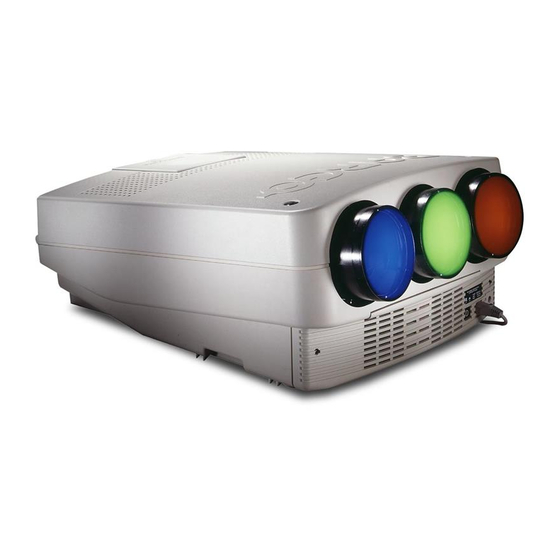
Page 9: Unpacking & Dimensions
Take the projector out of its shipping carton and place it on a table. Save the original shipping carton and packing material, they will come in handy if you ever have to ship your projector. For maximum protection, repack your projector as it was originally packed at the factory. -
Page 10: Projector Dimensions
Unpacking and Dimensions Projector dimensions (mm) 2 - 2 5975987A BARCODATA 708 260597... -
Page 11: Installation Guidelines
1.4m (4.6') to 7m (23') with an aspect ratio of 4 to 3. It leaves the BARCO factory, adjusted as a ceiling front projector for a screen width of 2.4m. Changing the image size from the factory preset requires a realignment of the projector. -
Page 12: Where To Install The Projector
To install the projector, apply always the BARCO kits which are specially designed for this function. BARCO ceiling support. Always use the BARCO ceiling support to attach your projector to the ceiling. (BARCO order number : R9827990) The installation instruction for this support is enclosed in the packet of the set. -
Page 13: Installation Set Up
Therefore, - pivote the top cover ± 60° - push the top cover to the front side of the projector until it jumps out of its hings. - Turn the top cover till 90° and lift it up. -
Page 14: Scan Adaptation
- Open the top cover (to remove it, see 'Gaining access to controls'. - To open the chassis, loosen both indicated retaining screws. Turn the chassis to the front of the projector until it grips in its locks. COMM PORT... - Page 15 - highlight 'service' with the control disk and press ENTER . The 'service mode menu' will be displayed - select with the control disk 'Projector set up' and press ENTER . The 'Projector set up menu' will be displayed. - Select with the control disk 'Identification' and press ENTER .
- Page 16 Installation Set Up 5975987A BARCODATA 708 260597...
-
Page 17: Projector Set Up
- Open the chassis (see installation set up) Password mode With a strap on the controller unit, the important projector adjustments can be protected with a password. When the password feature is enabled (strap mounted on both legs), the customer has to enter a password before he can enter the specific adjustment. - Page 18 Projector Set Up 5975987A BARCODATA 708 260597...
-
Page 19: Power (Mains) Connection
For continued protection against fire hazard : - replace with the same type of fuse - refer replacement to qualified service personnel Fuse type : 2 x T5A/250V (Barco order number : R314104) Switching on/off The projector is switched ON and OFF using the power (mains) switch ON/OFF. - Page 20 Power Connection 5975987A BARCODATA 708 260597...
-
Page 21: Installation Adjustments
INSTALLATION ADJUSTMENTS Entering the adjustment mode Press ADJUST to enter the adjustment mode. 5975987A BARCODATA 708 260597 Installation (only for qualified technician) Random Access Adjustment Installation Adjustments ADJUSTMENT MODE Select a path from below: GUIDED RANDOM ACCESS INSTALLATION SERVICE IRIS source 1 Select with then <ENTER>... -
Page 22: Overview Flow Chart Installation Mode
The projector displays the path selection menu. b) Using the local keypad. Press the ADJUST key. The projector displays the General access menu . Use the control disk to highlight enter ADJUST and press ENTER . The path selection menu will be displayed. - Page 23 'enter password'. When your password is correct, you get access to the 'Adjustment mode'. When the entered password is wrong, The message 'Wrong pass- word !!!' will be displayed. The projector stays on the previous selected item. Factory programmed password : 0000 b) adjusting the projector with the local keypad.
-
Page 24: Scheimpfug Adjustment
Installation Adjustments Scheimpfug adjustment The scheimpfug correction can be adjusted separately for the three tubes within 3 ranges: range 1 : 1.4 m (55") to 1.9 m (75"), optimum screen width 1.4 m (55") range 2 : 1.9 m (75") to 3.2 m (126"), optimum screen width 2.4 m (94") range 3 : 3.2 m (126") to 6 m (236"), optimum screen width 4 m (157") -
Page 25: Optical Lens Focusing
Optical lens focusing The optical focusing procedure is performed separately for each lens. The appropriate CRT will be switched on as the user proceeds through the optical focusing adjustment sequence. Each lens has two focus adjustment points, one at the rear of the lens and one at the front. -
Page 26: Raster Centering
Installation Adjustments Raster centering The raster must be centered on the CRT screen surface of each tube, therefore, it is necessary to look into the lenses. Caution : To avoid eye discomfort while performing these adjust- ments, reduce the contrast and gradually increase the brightness level until the raster becomes visible behind the image. -
Page 27: Crt Projection Angle Adjustment
CRT projection angle adjustment The projection angle of the red and blue CRT's is dependent on the desired size of the projected image. If the centers of green, blue and red do not coincide, the CRT projection angle must be adjusted. Never try to correct this misalignment with the shift correction or the static convergence controls. - Page 28 Installation Adjustments Loosen the four hexagon screws A, A', B and B', upper and lower fixation latch. These screws fasten the cooling house of the red tube. Pivot the red CRT until the center of the red image coincides with the center of the green image.
-
Page 29: Alignment Of The Projector
After finishing the installation adjustments procedure, the 'Path selection' returns on the screen. You are now able to start the alignment procedure for the projector. You have the choice between: - Guided Adjustment Procedure - Random Access Adjustment Procedure The result of both procedures will be the same. More explanation about both procedures is given in the owners manual. - Page 30 Installation Adjustments 7-10 5975987A BARCODATA 708 260597...
- Page 31 <ENTER> <EXIT> to return. SAFETY NOTICE RISK OF ELECTRICAL SHOCK G2 ADJUSTMENT SHOULD BE PERFORMED BY BARCO PERSONNEL, OR BARCO AUTHORIZED DEALERS. IF QUALIFIED, PRESS <ENTER> TO CONTINUE, OR IF NOT, <EXIT> TO RETURN. G2 ADJUSTMENT Use the potentiometers...
-
Page 32: Appendix A : G2 Adjustment
G2 Adjustment A green LED for each color is mounted on the driver board, below the CRT's. When selecting the G2 adjustment menu, these green LEDs must be out. If not, follow the procedure to adjust the G2 : - Loosen the retaining screws of the upper electronic chassis and pivot it to the lenses. - Page 33 MATERIAL SAFETY DATA SHEET MANUFACTURER'S NAME AND FSCM (Federal Supply Code for Manufacturer's) BARCO N.V. ADDRESS (Number, Street, City, State, and ZIP Code) Noordlaan 5 B-8520 KUURNE CHEMICAL NAME AND SYNONYMS Ethylenglycol & Glycerol CHEMICAL FAMILY Polyalcohols FEDERAL STOCK NUMBER (FSN) MIL-STD-1341/NATIONAL FIRE PROTECTION ASSOCIATION STD 704M SIGNAL FLAMMABILITY...
- Page 34 TRESHOLD LIMIT VALUE 100ppm EFFECTS OF OVEREXPOSURE EMERGENCY AND FIRST AID PROCEDURES STABILITY UNSTABLE STABLE INCOMPATABILITY (Materials to avoid) HAZARDOUS DECOMPOSITION PRODUCTS OCCUR HAZARDOUS POLYMERIZATION WILL NOT OCCUR STEPS TO BE TAKEN IN CASE MATERIAL IS RELEASED OR SPILLED WASTE DISPOSAL METHOD RESPIRATORY PROTECTION (Specific type) VENTILATION LOCAL EXHAUST...
Need help?
Do you have a question about the DATA 708 and is the answer not in the manual?
Questions and answers