Table of Contents
Advertisement
Quick Links
Advertisement
Table of Contents

Related Manuals for Swegon CONDUCTOR W1


Summary of Contents for Swegon CONDUCTOR W1
- Page 1 CONDUCTOR W1/W3 Technical Manual Updated: 2012-11-16 SW version 0.76...
-
Page 3: Table Of Contents
Introduction and Safety ........5 About this Manual ..........5 Product Design Changes ......... 5 Safety Precautions ..........5 Technical Description ......... 7 About Conductor W1/W3 ........7 Controller and Room Unit (thermostat) ....7 Installation Examples ..........10 Operating Mode ............11 Operating Modes ..........13 Functions ...............14... - Page 4 Contents...
-
Page 5: Introduction And Safety
(thermostat). The Service section is intended for personnel who are specially trained by Swegon. Product design changes Swegon reserves the right to change the specifications in the manual and change the design of the product without notice. Safety precautions Responsibility It is the responsibility of the user to do the following: •... - Page 6 Introduction and Safety 1 : 6...
-
Page 7: Technical Description
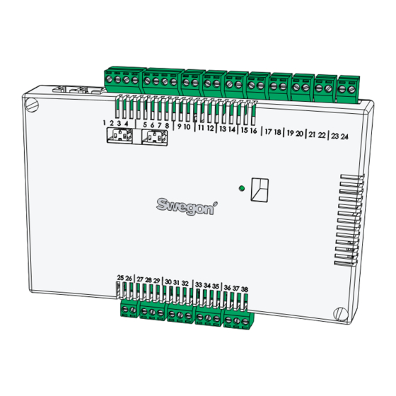
(W3)., especially adapted for partitioned offices and hotel rooms. It can operate independently or in combination with a central system. Controller and Room Unit (thermostat) The main components in the CONDUCTOR W1/W3 control system are a controller and a room unit (thermostat). Controller Figur 1. - Page 8 Technical Description The controller is equipped with inputs for connection of a condensation sensor, carbon dioxide sensor, window switch, presence detector and outputs for the connection of actuators for valves and air dampers. Up to twelve pairs of actuators (twelve for cooling + twelve for heating) can be wired to each controller.
- Page 9 Technical Description Room Unit Figur 3. Overview of the room unit (thermostat). Pos 1. Display Pos 2. Keypad. Pos 3. Temperature sensor. The room unit is simple to use and has an easy-to-interpret design that makes it user-friendly. The digital display shows the current preset temperature and airflow settings.
-
Page 10: Installation Examples
Technical Description Installation Examples The illustration below shows a typical arrangement of a complete installation with the CONDUCTOR W1/W3 control system. 24V AC Figur 4. Example of a CONDUCTOR W1/W3 installation. Item Component Quantity Description PARASOL 1192-B-HF Comfort module including cooling, heating and... -
Page 11: Operating Mode
Technical Description Operating Mode Applications These instructions deal with two different applications: W1 and W3. W indicates that both the applications are applicable to waterborne climate systems. A waterborne system provides the room with waterborne heating and cooling. The air-based systems which can be controlled in the W3 by means of connected damper actuators are only used to satisfy the demands on air quality, while the temperature of the supply air and extract air is kept constant. - Page 12 Technical Description The W3-application can be used either for offi ces or for hotel rooms. It is well-suited for systems with variable airfl ow (VAV) with both supply air and extract air. Four outputs are used to control heating, cooling, supply and extract air.
-
Page 13: Operating Modes
Technical Description Operating Modes There are a variety of functions built into the CONDUCTOR: • MAN, manual mode. • AUTO, automatic mode. • ECON, energy-saving mode. • Stand-by mode. • EMERG, emergency mode. MAN, Manual operating mode. Whenever the CONDUCTOR registers occupancy in the room in response to signals from a presence detector, the user can regulate the temperature and airflow rate by entering settings in the room unit. -
Page 14: Functions
The supply air is normally shut off. The EMERG mode can only be managed in control systems that are connected to a main control system via ModBus RTU. Functions There are a variety of functions built into the CONDUCTOR W1/W3: • Exercising of valves •... - Page 15 Technical Description Frost protection The function involves the following: Heating operation is started at a predefined room temperature in order to counteract the risk of damage that otherwise can arise due to freezing. Change over The function involves the use of only one valve actuator which should be wired to the cooling output terminal.
-
Page 16: Technical Data Re Controller
Technical Description Technical Data CONDUCTOR RE Controller Technical data applicable to the CONDUCTOR RE controller (W1/W3) is specified below. Item Data Designation CONDUCTOR RE (W1/W3) -40 °C to +80 °C Storage temperature -20 °C to +50 °C Operating temperature Degree of protection IP 32 Dimensions 121 x 193 x 44 mm... -
Page 17: Technical Data Ru Room Unit
Technical Description CONDUCTOR RU room unit (thermostat) Item Data Designation: CONDUCTOR RU -40 °C to +80 °C (*) Storage temperature 0 °C to +50°C Operating temperature Degree of protection IP 20 Dimensions 86 x 100 x 32 mm Supply voltage 12 V, 4 size AAA batteries Actual value, range +10 °C to +32°C... - Page 18 Technical Description 2 : 18...
-
Page 19: Installation
Installation Installation Ordering, delivery and electrical installation Ordering key, Control equipment Item Data Controller W1/W3 CONDUCTOR RE (aa) Room unit (Thermostat) CONDUCTOR RU Ordering Key, Accessories Item Data Valve SYST VD 115-CLC Valve actuator LUNA a AT-2 Ventilation damper incl. SYST CRTc 9 (aaa)-2-CM-24 damper actuator Adapter, actuator/valve... -
Page 20: Preparations
The electrical contractor or the systems contractor provides a 230 V earthed outlet for transformer, a fitted junction box for the room unit (thermostat) and possible external cables. Preparations The CONDUCTOR W1/W3 should be installed in steps as follows: To mount the controller. To connect units. Commissioning. -
Page 21: Step 1, To Mount The Controller
Installation Step 1, To mount the controller. Mounting on a DIN rail If a DIN rail is mounted on the comfort module or at another suitable location, the controller should be fastened to this rail. Figur 1. To mount the controller. Pos 1. - Page 22 Installation To be installed above a false ceiling If a DIN rail is NOT available pre-mounted or is not available, the controller can be appropriately mounted above the false ceiling (not on the module). Figur 2. To mount the controller. Pos 1.
-
Page 23: Step 2, To Connect The Units
Installation Step 2, Installation of units The following units should be connected to the detachable wiring terminals of the controller: 24 V AC Figur 3. Overview of the units. Pos 1. Valve actuator for cooling water. Pos 2. Valve actuator for heating water Pos 3. -
Page 24: Step 3, Commissioning
Installation Step 3, Commissioning To connect the mains power supply cable Connect the transformer’s mains power supply cable to an electric outlet. To insert batteries in the room unit (thermostat) The room unit is normally supplied with electric current from four size AAA batteries. - Page 25 Installation Booting As soon as the controller and the room unit have been energized, the system boots up and the main view is shown in the display of the room unit. The controller is in the AUTO operating mode when the system has finished booting.
-
Page 26: Step 4, To Install The Room Unit (Thermostat)
Installation Step 4, To install the room unit (thermostat) The room unit contains a temperature sensor used for measuring the current room temperature. In order for the controller to regulate the temperature in relation to the preset setting, the room unit must be installed in such a way that enables it to correctly measure the temperature. -
Page 27: The Menus Of The Room Unit Ru (Thermostat)
The menus of the room unit The menus of the room unit (thermostat) The main image and the key pad of the room unit Figur 1. Overview of the main image of the room unit. Pos 1. Cursor key for moving DOWN. Pos 2. - Page 28 The menus of the room unit Current airflow The field shows the present airflow setting. Symbol for low airflow. Symbol for normal airflow. Symbol for high airflow. Operating mode The field shows the current operating mode. The field is empty if the unit is operating in the manual mode.
-
Page 29: Overview Of The Menu System Of The Ru
The menus of the room unit Overview over the menu system of the room unit. The menu system of the room unit consists of the following menus with associated submenus. • Main menu • Service menu Main menu and Service menu Main menu Setup Enter code... -
Page 30: Navigating In The Menus Of The Room Unit
The menus of the room unit Navigating in the menus of the room unit Go to the main menu Main menu Setup <Exit Select> Figur 2. Main image and Main menu. Press on the OK key while the main image is shown in the display and hold the key pressed down for 3 seconds. -
Page 31: Changes In The Main Image
The menus of the room unit Changes in the Main image To set the desired room temperature Figur 4. The Main image Check that the main image is shown in the display. Press on: The ▲ UP key to raise the temperature. •... -
Page 32: Changes And Settings In The Service Menu
The menus of the room unit Changes and settings in the Service menu To set the air damper for supply air and to change the K-factor Service Menu Econ SA % Norm SA % Regulator adjust Boost SA % Settings Select>... - Page 33 The menus of the room unit Adjust the air damper for extract air and change the value for offset Service Menu Econ EA % Norm EA % Regulator adjust Boost EA % Settings Select> <Exit <Previous OK select Next> Figur 7. Image for selecting Regulator adjustment settings and image for setting the air damper for extract air and the value for offset.
- Page 34 The menus of the room unit To set the existing room temperature Service Menu Temp C Regulator adjust Settings <Prev. Select> <Exit OK select Next> Figur 8. Image for selecting Regulator adjustment settings and image for setting the existing room temperature. Go to the Service menu.
- Page 35 The menus of the room unit Change ModBus address in room unit for RU Settings ModBUS ModBUS [First] RF pair-up Select> <Exit <Exit Figur 9. Image for selecting to change the ModBus address and the MB address image. The unit must be assigned an adress to enable connecting it up to ModBUS, when the room unit is connected via cable to the controller.
- Page 36 The menus of the room unit Connect units room unit (RU) to controller (RE) ModBUS RF pair-up RF pair-up 0 0 0 0 RF Quality <Exit Select> <Exit > Figur 10. Image for selecting RF pair-up and the RF pair-up image. The units must be connected together in order to control the controller by means of a hand-held micro terminal.
- Page 37 The menus of the room unit Test the radio connection ModBUS RF connection RF pair up RF pair up: 100 Language Select> Start <Exit <Exit Figur 11. Imaage for selecting the RF pair-up and the RF connection image. If no cable is connected between the controller and the room unit, the two will communicate with one another via radio signals.
- Page 38 The menus of the room unit Change language RF Quality Language Language [Swedish] FirstTime func Select> <Exit <Exit Figur 12. Image for selecting Language and the Language image. Go to the Service menu. Highlight Settings. Press OK or on the ► Right key. To highlight Language.
- Page 39 The menus of the room unit Calibrate temperature Temp. calibration Language FirstTime func [0,0] Temp. calibration <Exit Select> <Exit Figur 14. Image for selecting calibrate temperature and the Temp. calibration image . The purpose of the Calibrate temperature action is to ensure that the temperature reading is in agreement with the actual room temperature.
- Page 40 The menus of the room unit Change parameters General param. Parameter Value P_1902 Appl. Param. 1 or 2 room units Alarms Min 0 Max 2 Select> <Exit <Exit Change> Figur 16. Image for selecting changes in the application parameters and typical parameter image.
-
Page 41: Service
This section is intended only for use by personnel who are specially trained by Swegon. Parameters In order to control the functions in the CONDUCTOR W1/W3, there are a number of parameters, which can be changed in order to optimize the current installation. In the display of the room unit (thermostat) every parameter is shown in accordance with the figure below. - Page 42 Service Display image Description Indicates which application the P_106 controller is set to run. 1 = W3 Application type 2 = W1 max 14 Indicates the status of the relay P_107 for the EMERG mode. 0 = Open Relay at emer. 0=Op. 1=Cl. 2=No act. 1 = Closed 2 = No action max 2...
-
Page 43: Application Parameters W1
Service Application parameters W1 Application parameters are parameter-specific for the selected application. Display image Description Indicates how the climate P_1101 system should operate for heating and cooling. System1=H,2=C,3=ChOv,4=HC 1 = Heating only 2 = Cooling only max 4 3 = Change-over function 4 = Heating/Cooling Indicates whether one or P_1102... - Page 44 Service Display image Description Indicates which lowest P_1119 16 C temperature is possible to adjust manually on the room Room unit’s min temperature unit in the MAN operating mode. max 20 Indicates which highest P_1120 28 C temperature is possible to adjust manually on the room Room unit’s max temperature unit in the MAN operating...
- Page 45 Service Application parameters W3 Application parameters are parameter-specific for the selected application. Display image Description Indicates how the climate P_1001 system should operate for heating and cooling. System1=H,2=C,3=ChOv,4=HC 1 = Heating only 2 = Cooling only max 4 3 = Change-over function 4 = Heating/Cooling Indicates whether one or P_1002...
- Page 46 Service Display image Description Offset voltage for 0% supply P_1018 airflow. (Dissolution=50mV) SA mV at 0% output max 5000 Offset voltage for 100% supply P_1019 10000 mV airflow. (Dissolution=50mV) SA mV at 100% output 5000 max 10000 Offset voltage for 0% extract P_1020 airflow.
- Page 47 Service Display image Description Indicates by how much the P_1029 room temperature actual value should rise above the setpoint Boost at temp. over setpoint (K) in order for the controller to switch from AUTO to BOOST. max 10 Indicates whether time-adjusted P_1034 fl ow boost is accessible.
- Page 48 Service Display image Description Indicates the temperature P_1046 setpoint applicable to the Night cool function. Night cool temp set point max 20 Indicates the supply airflow for P_1047 “night cool”. Night cool flow SA % max 100 Indicates the extract airflow for P_1048 “night cool”.
-
Page 49: Indications On The Controller
Service Indication on the controller There are two indicating LEDs on the controller, one on the front (No.1) and under the lid (No.2). The indications that can be shown, their importance and their relation to the DIP switches (DIP) is as follows: DIP 1 DIP 2 Explanation Remarks Green... -
Page 50: Troubleshooting
Service Trouble shooting An alarm is initiated when an error arises in the control system. There are two types of alarms: • General alarms. • Application alarms. Trouble shooting of the control system should always begin with investigating whether any alarm has been initiated and if so which. Certain alarms are automatically reset (Auto) after the cause of the error has been remedied, while other alarms have to be manually (Man) reset. - Page 51 Service Alarm Alarm text Description / Remedial Resetting Cause measure Short circuit X11 Connected component is Troubleshoot to find Man. defectiveive. the faulty component and replace the component. Short circuit X12 Connected component is Troubleshoot to find Man. defectiveive. the faulty component and replace the component.
-
Page 52: Modbus Register W1
Service Modbus-register W1 The information listed below applies when the CONDUCTOR W1 is connected to a so-called Mod- Bus system. ModBus-register W1 applies to software after 076 Input Status Discrete Input (1 bit) Read only Modbus Name Min/Max Remarks Default... - Page 53 Service ModBus-register W1 applies to software after 0.76 Holding 16 bit integer register register Modbus Name Min/Max Remarks Default 1x0026 Short circuit X11 ALARM, requires HW reset 1x0027 Short circuit X12 ALARM, requires HW reset 1x0028 Short circuit X13 ALARM, requires HW reset 1x0029 Short circuit X14 ALARM, requires HW reset...
- Page 54 Service ModBus-register W1 applies to software after 0.76 Holding 16 bit integer register register Modbus Name Min/Max Remarks Default 4x0001 Relay in Emergency 0=Close, 1=Open, 2=No Action 4x0002 Application transition 1=Normal, 3=Manual, 4=Stand-by, 5=Emergency, 6=NightCool 4x0003 Room number 4x0004 Valve exercise 0/72 Valve exercise 0=Not used (hours) 4x0005...
- Page 55 Service ModBus-register W1 applies to software after 0.76 Input register 16 bit integer register Read only Modbus Name Min/Max Remarks Default 4x0037 Not used 4x0038 Not used 4x0039 Not used 4x0040 Not used 4x0041 Not used 4x0042 Not used 4x0043 Not used 4x0044 Not used...
- Page 56 Service ModBus-register W1 applies to software after 0.76 Input register 16 bit integer register Read only Modbus Name Min/Max Remarks Default 3x0001 Component Name ID 0/10 ID for type of controller in Conductor and 00003 Wise system 3x0002 - 0017 Component Name 0/999 Name built of max 16 chr, exch chr (ASCII...
- Page 57 Service ModBus-register W1 applies to software after 0.76 Coil Status Discrete Output (1 bit) Modbus Name Min/Max Remarks Default 3x0057 Not used 3x0058 Not used 3x0059 Not used 3x0060 Room temp (degC) 3x0061 Change over temp (degC) 3x0062 Not used 3x0063 Copy of Input Status 1-16 0/65535...
-
Page 58: Modbus Register W3
Service Modbus-register W3 ModBus-register W3 applies to software after 0.76 Input Discrete Input (1 bit) Read only Status Modbus Name Min/Max Remarks Default 0x0001 Not used 0x0002 SA Emergency action 0x0003 EA Emergency action 0x0004 Not used 0x0005 Economy mode 0=Unavailable, 1= Available 0x0006 Timer Function... - Page 59 Service ModBus-register W3 applies to software after 0.76 Input Status Discrete Input (1 bit) Read only Modbus Name Min/Max Remarks Default 1x0031 Radio chip broken ALARM, requires HW reset 1x0032 Parameter file revision ALARM, requires HW reset 1x0033 Parameter file format ALARM, requires HW reset 1x0034 No ModBus ID...
- Page 60 Service ModBus-register W3 applies to software after 0.76 Holding 16 bit integer register register Modbus Name Min/Max Remarks Default 4x0001 Relay in Emergency 0=Close, 1=Open, 2=No Action 4x0002 Application transition Read Only: 2=Auto Economy, 3=Auto boost, 5=Timer-function Read/Write 1=Auto Normal, 4=Manual, 6=Stand-by, 7=Emergency, 8=Night Cool 4x0003 Room number...
- Page 61 Service ModBus-register W3 applies to software after 0.76 Holding 16 bit integer register register Modbus Name Min/Max Remarks Default 4x0037 Normal flow EA 0/100 4x0038 Economy flow SA 0/100 4x0039 Economy flow EA 0/100 4x0040 Night cool flow SA 50/100 4x0041 Night cool flow EA 50/100...
- Page 62 Service ModBus-register W3 applies to software after 0.76 Input register 16 bit integer register Read only Modbus Name Min/Max Remarks Default 3x0001 Component Name ID 0/10 ID for type of controller in Conductor and Wise system 3x0002 - 0017 Component Name 0/999 Name built of max 16 chr, exch chr (ASCII standard)
- Page 63 Service ModBus-register W3 applies to software before 0.76 Input register 16 bit integer register Read only Modbus Name Min/Max Remarks Default 3x0057 Not used 3x0058 Not used 3x0059 Not used 3x0060 Room temp (degC) 3x0061 Change over temp (degC) 3x0062 Not used 3x0063 Copy of Input Status 1-16...
Need help?
Do you have a question about the CONDUCTOR W1 and is the answer not in the manual?
Questions and answers