Table of Contents
Advertisement
Advertisement
Table of Contents

Related Manuals for Swegon P.LEMMENS TAC4 DG


Summary of Contents for Swegon P.LEMMENS TAC4 DG
- Page 1 TAC4 DG + RC...
- Page 3 TAC4 DG + RC Installation and user’s manual...
-
Page 5: Table Of Contents
TABLE OF CONTENTS FUNCTIONALITIES OF THE REGULATION ................... 5 GENERAL MAINTENANCE INSTRUCTIONS ..................7 2.1. General information ......................... 7 2.1.1. General schematic of the HR units ..............7 2.1.2. Label located inside the cover of the control panel 3 ........8 REGULATION: CONFIGURATION –... - Page 6 3.12. Regulation for external coil(s) (SAT TAC4 BA/KW option) ............41 3.13. Display on the RC TAC4 ........................ 41 3.14. Fan failure alarm ..........................42 3.14.1. Wiring diagram .................... 42 3.15. Actual airflow / pressure output signals ..................43 3.16. Advanced setup ..........................44 Appendix: Installation control datasheet (to be filled in after starting the installation) ......
-
Page 7: Functionalities Of The Regulation
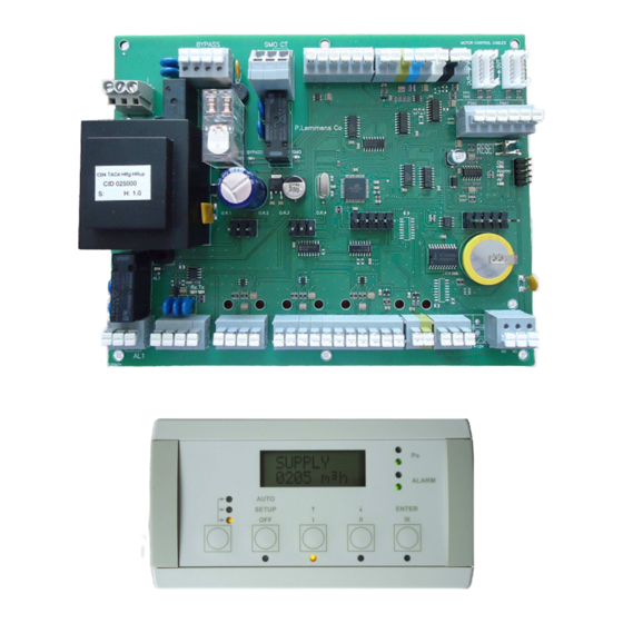
1. FUNCTIONALITIES OF THE REGULATION The TAC4 DG controller is mounted in the units of series HRglobal, HRup and HRflat. This handbook describes the functionalities of the TAC4 DG when using an RC TAC4 display. The TAC4 DG with RC TAC4 controller provides the following features: Monitoring of the fans (exhaust and supply) in chosen working mode: constant airflow (CA), constant pressure (CPs) or constant airflow linked to 0-10V signal (LS) (e.g. - Page 8 Installation and user’s manual TAC4 DG + RC SAT TAC4 WIFI Option: communication with MODBUS TCP/IP protocol on wireless WIFI network. SAT TAC4 KNX Option: KNX Communication See separate installation manual for each of these options.
-
Page 9: General Maintenance Instructions
2. GENERAL MAINTENANCE INSTRUCTIONS 2.1. General information 2.1.1. General schematic of the HR units HRflat HRup HRglobal 1. Main switch for power supply fans and control 2. Main switch for power supply to pre (KWin) and/or post (KWout) heating coils (options) 3. -
Page 10: Label Located Inside The Cover Of The Control Panel 3
Installation and user’s manual TAC4 DG + RC Schematic of the T° sensors positioning in the HRg unit To allow easier identification of the temperature sensors 4 different wire colours are used: T1 : black wire T2 : white wire T3 : blue wire T4 &... -
Page 11: Regulation: Configuration - Wiring - Operating
3. REGULATION: CONFIGURATION – WIRING – OPERATING The regulation is delivered fully factory pre-wired. Nevertheless, the TAC4 RC (remote control) and the I/O signals if any must still be wired by the installer. 3.1. Connecting the RC TAC4 to the CB4 TAC4 DG circuit The connection between the various circuits is made by a communication bus. -
Page 12: Wiring Diagram To Connect The Rc Tac4 Rec To The Tac4 Dg Circuit
Installation and user’s manual TAC4 DG + RC Caution: • The RC box is class IP20 and cannot be installed outdoors as such. If you wish to install it outdoors you need to fasten inside a proper watertight box. • The configuration data is stored in the TAC4 DG circuit. - Page 13 TAC4 DG circuit is master RC TAC4 is master Control Visualization Control Visualization Wiring diagram Contact closed = TAC4 DG circuit master Contact open = RC TAC4 master Caution: Use gold-plated contact only The use of this contact enables to switch automatically from RC TAC4 master to TAC4 DG master. Using this you can for instance: •...
-
Page 14: Fan Control
Installation and user’s manual TAC4 DG + RC 3.3. Fan control 3.3.1. Working modes The various working modes give the user the choice on how the airflow must be modulated according to your application. In all the working modes the supply fan will operate according to the assigned mode and parameters. The airflow of the exhaust fan will then equal to a percentage of the actual airflow of the supply fan (noted %EXH / SUP for ratio between exhaust and supply airflows). -
Page 15: Ca Mode: Setup, Operating Instructions And Wiring Diagrams
3.3.2. CA Mode: setup, operating instructions and wiring diagrams 3.3.2.1. Setup CA mode ↑, ↓ The setup is made by means of the LCD screen and the 4 knobs SETUP, and ENTER of the RC. To start the setup: - Enter in the setup mode using the left knob on the diagram so that the SETUP LED lights. - Page 16 Installation and user’s manual TAC4 DG + RC 3.3.2.2. Operating CA mode with RC TAC4 master • One of the 3 assignment constant airflows (m³h K1, m³h K2 and m³h K3) is selected using the I / II / III knobs of the RC TAC4.
- Page 17 c) Wiring several circuits to 3 external contacts K1 closed airflow m h K1 K2 closed airflow m h K2 K3 closed airflow m h K3 K1/K2/K3 open soft stop Caution K1/K2/K3: Use gold-plated contacts only. d) Wiring several circuits to 1 COM4...
-
Page 18: Ls Mode: Setup, Operating Instructions And Wiring Diagrams
Installation and user’s manual TAC4 DG + RC 3.3.3. LS Mode: setup, operating instructions and wiring diagrams 3.3.3.1. Setup LS mode ↑, ↓ The setup is made by means of the LCD screen and the 4 knobs SETUP, and ENTER of the RC. To start the setup: - Enter in the setup mode using the left knob on the diagram so that the SETUP LED lights. - Page 19 3.3.3.2. Operating LS mode with RC TAC4 master The assignment value for the supply constant airflow is a function of a 0-10V signal connected to terminals K2 of the TAC4 DG circuit. The link between voltage and airflow is linear. The exhaust constant airflow is equal to %EXH/SUP of the supply airflow (except if 2 separate 0-10V signals are used to determine exhaust and supply constant airflows, see advanced setup).
- Page 20 Installation and user’s manual TAC4 DG + RC 3.3.3.3. Operating LS mode with TAC4 DG master The assignment value for the supply constant airflow is a function of a 0-10V signal connected to terminals K2 of the TAC4 DG circuit. The link between voltage and airflow is linear. The exhaust constant airflow is equal to %EXH/SUP of the supply airflow (except if 2 separate 0-10V signals are used to determine exhaust and supply constant airflows, see advanced setup).
-
Page 21: Cps Mode: Setup, Operating Instructions And Wiring Diagrams
3.3.4. CPs Mode: setup, operating instructions and wiring diagrams 3.3.4.1. Setup CPs mode ↑, ↓ The setup is made by means of the LCD screen and the 4 knobs SETUP, and ENTER of the RC. To start the setup: - Enter in the setup mode using the left knob on the diagram so that the SETUP LED ignites. - Page 22 Installation and user’s manual TAC4 DG + RC INIT EXH Resetting of CPs assignment on exhaust air busy (if EXHAUST or SUP+EXH was selected at step 5). xx,x V After 1 minute the system will memorize the pressure measured by the sensor INIT EXH corresponding to the nominal airflow.
- Page 23 b) Wiring to several circuits in parallel 0-10V signal, maximum impedance allowed: 1500 Ω (*) K2 3.3.4.3. Operating CPs mode with TAC4 DG master • The start/stop of the fans is controlled by entry K1 of the TAC4 DG circuit. •...
-
Page 24: Time Slots Schedules
Installation and user’s manual TAC4 DG + RC 3.4. Time slots schedules 3.4.1. Definition The TAC4 DG regulation allows to configure 4 time slots (TS) and to set OFF days. For each time slot select: In CA mode: which airflow by selecting m³h K1 / m³h K2 / m³h K3 / OFF (stop) In LS mode: the link LS (percentage of the nominal link) and the rate of the exhaust airflow by the supply airflow. - Page 25 If LS mode TIME 1: Enter TS1 starting time. If empty time slot is inactive. --:-- SET VAL. For TS1, enter coefficient (%) applied to the base link configured between V value and airflow value (cfr m³/h≡Vmin and m³/h≡Vmax in setup). LS 000% Select 000 to stop both supply and exhaust fans.
- Page 26 Installation and user’s manual TAC4 DG + RC TIME 3: Enter TS3 starting time. If empty time slot is inactive. --:-- SET VAL. For TS3, enter coefficient (%) applied to the pressure assignment defined in the basic setup. CPs 000% Select 000 to stop both supply and exhaust fans.
- Page 27 For all working modes Select Y if you wish to activate the day OFF option DAY OFF If DAY OFF option activated : for MONDAYs select AUTO (normal time slots setup is MONDAY active) or OFF (no ventilation on Monday) AUTO TUESDAY If DAY OFF option activated : for TUESDAYs select AUTO (normal time slots setup is...
-
Page 28: Switching From Manu To Auto Mode (Scheduler)
Installation and user’s manual TAC4 DG + RC 3.4.3. Switching from MANU to AUTO mode (scheduler) 3.4.3.1. Via RC TAC4 master AUTO-MANU Push 4 seconds on the left push- 4 sec. pushing button to switch to another mode. 3.4.3.2. Via TAC4 DT master IN5 open: MANUAL mode active IN5 closed: AUTOMATIC mode active... -
Page 29: Alarms
3.5. Alarms 3.5.1. Alarm types Type 1: Alarm indicating a fan failure. This alarm indicates a failure of fan Fx. This problem is usually caused by the motor. If not, the failure can be caused by an internal cable or by the TAC4 DG circuit. - Page 30 Installation and user’s manual TAC4 DG + RC Type 4: Alarm indicating the system cannot fulfil the assignment. The assignment (keeping certain airflow or a certain pressure constant) cannot be fulfilled because the upper or lower limit of the fan’s working zone has been reached. See 4 in table below.
- Page 31 This alarm indicates that the supply T° set point cannot be reached (actual T° lower than set point during 15 minutes while post heating is at maximum) See 12 in table below. Type 13 and 14: Alarm indicating anti-frosting alert (only with KWin or BAin or if modality of modulating by- pass in anti-frosting protection).
-
Page 32: Alarm Table
Installation and user’s manual TAC4 DG + RC 3.5.2. Alarm table Actions on RC TAC4 Actions on the TAC4 DG circuit Action on fans Type Display (1) LED Pa R2 relay LED AF ALARM ALARM relay of SAT3 (O.R.1) ALARM Alarm Stopped FANx... -
Page 33: Wiring Diagrams
3.5.3. Wiring diagrams: O.R.1 O.R.2 3.5.4. Fire alarm The TAC4 DG control can be connected to a fire detection system to: - stop/start the supply/exhaust fans according to fire regulations - set the airflows in case of fire alarms according to fire regulations - allow firemen to overrule the existing setup and start/stop the fans as needed. -
Page 34: Boost Function
Installation and user’s manual TAC4 DG + RC Wiring diagram of fire alarm If IN3 12V closed = fire alarm activated (this logic can be reversed via advanced setup menu). Default, if IN3 – 12 V closed and: • IN7 - 12V closed = force start the supply fan(s) at pre-programmed airflow (1). •... -
Page 35: Operating Description
The by-pass can work in “all or nothing” or in proportional mode (modulating by-pass modality, modifiable in the advanced setup, equal to « FREECOOL», by default, or « AF+FREECOOL »). In proportional mode, the supply freecooling temperature is configured in the setup and the opening of the by-pass will vary to keep constant this temperature. -
Page 36: Opening / Closing Of Dampers (Ct Option) At Inlet
Installation and user’s manual TAC4 DG + RC By-pass status: by-pass by-pass closed partially or completely open 3.8. Opening / closing of dampers (CT option) at inlet The opening and closing of (a) damper(s) mounted at both supply and exhaust air inlets are automatically managed by the TAC4 DG regulation. -
Page 37: Anti-Frost Protection Via Regulation Of The By-Pass Opening
• T°(T3) < 1°C: the supply airflow is stopped for as long as T°(T3) < +2°C during 5 minutes. In these conditions LED AF is blinking. All these temperature SET values can be modified using ADVANCED SETUP (for ADVANCED SETUP manual www.lemmens.com). -
Page 38: Anti-Frost Protection With 1 Internal Electrical Pre-Heating Coil Kwin (Option)
Installation and user’s manual TAC4 DG + RC HRglobal 800 HRglobal 4000 T1[°C] T3[°C] T5[°C] RHS[%] % airflow in bypass T1[°C] T3[°C] T5[°C] RHS[%] % airflow in bypass 16,4 29,4 16,5 29,3 16,6 19,1 16,7 17,1 12,1 17,1 12,8 10,06 12,9 10,07 8,67... -
Page 39: Anti-Frost Protection With 1 External Hydraulic Pre-Heating Coil Bain (Option)
If CA and LS mode: reduction of in and outgoing airflows to 66% of the assigned airflows. If CPs Mode: reduction to 75% of the assigned pressure. This setup is maintained during 15 minutes, after which the 100% airflow/pressure assignment is re- established. -
Page 40: Wiring Diagrams
Installation and user’s manual TAC4 DG + RC • A post-ventilation of the coil function is available (see advanced configuration): When fans are requested to stop, first the electrical coils are shut down, then the fan operate for 90 seconds (minimum value) before stopping. -
Page 41: Wiring Diagrams
Control features of the TAC4 DG: • Monitoring the 3-way valve to keep assignment T° constant using supplied sensor T° value. • Engaging a relay to start a water circulator (output SAT 3 O.R.3 on i/o module - see § 3.11.1) •... - Page 42 Installation and user’s manual TAC4 DG + RC • Wiring of supply air T° sensor to TAC4 DG circuit: • Switching of a relay to control the circulator (SAT3 O.R.3 relay): • Possibility to stop the post-heating with an external contact: Contact closed = post-heating OFF Contact open = post-heating ON...
-
Page 43: Regulation For External Coil(S) (Sat Tac4 Ba/Kw Option)
3.12. Regulation for external coil(s) (SAT TAC4 BA/KW option) Via option SAT TAC4 BA/KW it is possible to control one or two external (from the unit) heat exchanger(s): One post-heating water coil One post-cooling water coil One post-heating/post-cooling coil (reversible coil) One post-heating coil + one post-cooling coil (separate) One electrical coil One electrical coil + one post-cooling water coil... -
Page 44: Fan Failure Alarm
Installation and user’s manual TAC4 DG + RC 3.14. Fan failure alarm It is possible with a SAT3 mounted on the TAC4 DG (option) to provide the fan status (control if actual delivered airflow > 20% of airflow assignment) or if they are stopped, using the R3 relay of one of the SAT3 (O.R.2). This feature provides an increased safety with regard to the start instruction control, because there is a control on the fact that the fan is actually running (closed loop principle). -
Page 45: Actual Airflow / Pressure Output Signals
3.15. Actual airflow / pressure output signals A 0-10V signal representing the actual airflow or the actual pressure delivered by one of the selected fans with a linear relation is a standard feature. The output signals are located between terminals OUT1/OUT2 and GND on the TAC4 DG circuit. Default setup: OUT1 = airflow fan 1 (supply fan) and OUT2 = pressure fan 1 (supply fan). -
Page 46: Advanced Setup
Installation and user’s manual TAC4 DG + RC 3.16. Advanced setup The advanced configuration allows modifying the parameters not present in the basic configuration. Warning: using this feature requires a good knowledge of the TAC4 DG control system. - Stop fans if pressure alarm activated - Fans start torque - Prevent stop of the fans (deactivation of the softstop function) - Fire alarm configuration... -
Page 47: Appendix: Installation Control Datasheet (To Be Filled In After Starting The Installation)
Appendix: Installation control datasheet (to be filled in after starting the installation) To facilitate any future intervention, specify in this table all settings specific to your installation. Please keep this document handy before contacting us for any problem. Without this could not be able to help you. Configuration parameters: HR model Working mode... - Page 48 P. LEMMENS COMPANY S.A. Parc Industriel de Sauvenière, 102, Chaussée de Tirlemont, B-5030 GEMBLOUX TEL. : +32 (0) 81 62 52 52, FAX : +32 (0) 81 62 52 53 www.lemmens.com © PLC 02/2015 - Cid 050034...
Need help?
Do you have a question about the P.LEMMENS TAC4 DG and is the answer not in the manual?
Questions and answers