Table of Contents
Advertisement
Advertisement
Table of Contents

Summary of Contents for TEXA KONFORT 744
- Page 1 KONFORT 744 Recharging ang Maintenance Technical manual www.elektropartner.com...
- Page 2 ENGLISH..............7...
-
Page 4: Table Of Contents
1.2.6 Fire and Explosion Hazard...............11 1.2.7 Noise Hazard....................11 1.2.8 High Voltage Hazard.................11 1.2.9 Poisoning Hazard..................12 1.3 General User and Maintenance Warnings...........12 2 KONFORT 744 USER SAFETY............13 2.1 Glossary....................13 2.2 General Rules..................13 2.3 Operator Safety..................14 2.4 Device Safety..................14 2.5 Workplace Safety.................15 2.6 Guidelines for the handling the refrigerants and user safety....15... - Page 5 6.3 Rear view.....................23 6.3.1 Containers....................24 6.4 Left Side View..................24 7 INSTALLATION.................25 7.1 Unwrapping the Device................25 8 SETTING UP BEFORE USING............26 8.1 Scale Locking/unlocking...............26 8.2 Refrigerant tank housing..............26 8.3 Moving the Device................32 8.4 Positioning....................32 8.5 Connection to the Power Mains............33 8.6 Entering the SD CARD.................33 8.7 How to Load the Paper into the Printer..........33 8.8 How to Fill the Bottles................34 8.9 Language Setup...................34...
- Page 6 13.1.1 How to Replace the Vaccum Pump Oil...........45 13.1.2 Replacing the Paper in the Printer............45 13.2 Periodical Checks................45 14 DISPOSAL..................47 14.1 How to Dispose of the Device............47 14.2 How to Dispose of the Recycled Materials.........47 15 TECHNICAL FEATURES..............48 16 LEGAL NOTICES................50...
-
Page 8: Revision Of The Manual
KONFORT 744 RECHARGING AND MAINTENANCE STATIONS TECHNICAL MANUAL REVISION OF THE MANUAL This document is review 01 of the technical manual for the KONFORT 744 charging stations. Issue date: 01/09/2016... -
Page 9: Introduction
INTRODUCTION Dear Customer, We would like to thank you for choosing a TEXA product for your workshop. We are certain that you will get the greatest satisfaction from it and receive a great deal of help in your work. Please read through the instructions in this manual carefully and keep it for future reference. -
Page 10: General Safety Regulations
1 GENERAL SAFETY REGULATIONS 1.1 Glossary • Operator: qualified individual, in charge of using the device/tool. • Machine/device/tool: the product purchased. • Workplace: the place where the operator must carry out her/his work. 1.2 Operator Safety Regulations 1.2.1 General Safety Regulations •... -
Page 11: Hazards Caused By Moving Parts
Safety Precautions: • Always make sure that the vehicle is in neutral gear (or that it is set in parking position in case of a vehicle equipped with automatic transmission). • Always activate the hand brake or parking brake on the vehicle. •... -
Page 12: Fire And Explosion Hazard
1.2.6 Fire and Explosion Hazard The following are potential fires and/or explosion hazards: • The types of fuel used by the vehicle and the vapours released by these fuels. • The refrigerants used by the A/C system. • The acid in the vehicle batteries. Safety Precautions: •... -
Page 13: Poisoning Hazard
• Work with dry hands only. • Keep conductive liquids away from the engine while working. • Never leave tools on the battery in order to avoid accidental contacts. 1.2.9 Poisoning Hazard The hoses used to extract the refrigerants can release toxic gases, dangerous to the operator if exposed to temperatures higher than 250 °C or in case of a fire. -
Page 14: Konfort 744 User Safety
• The operator must have fully read and understood the information and the instructions described in the technical documentation provided with the device. • The equipment must be used only by personnel properly trained by TEXA S.p.A. or through courses that are specifically approved by TEXA S.p.A. -
Page 15: Operator Safety
2.3 Operator Safety The use of refrigerants may cause serious risks for your health. Detailed medical and safety information can be obtained from the manufacturers of the lubricants and refrigerants. SUFFOCATION Inhaling large amounts of R744 (carbon dioxide, CO2) refrigerant may be harmful due to its low content of oxygen. -
Page 16: Workplace Safety
• Make sure you use the correct refrigerant for the vehicle you are working on. • Connect the hoses correctly by following the colours indicated: Blue hose - LP connection, red hose - HP connection. • Make sure all the valves are closed before connecting the device to the A/C system or to an external cylinder. -
Page 17: Safety Devices
2.7 Safety Devices The KONFORT 744 recharging stations are equipped with the following safety features: • Emergency button: it allows you to cut off the power supply from the mains in case of emergency or in order to carry out maintenance operations. -
Page 18: Normative Information
3 NORMATIVE INFORMATION Simplified EU Declaration of Conformity The manufacturer, TEXA S.p.A., declares that the type of KONFORT 744 equipment complies with the following directives: • PED 2014/68/EU • Machinery directive 2006/42/EC • Low voltage directive 2014/35/EU • RED 2014/53/UE •... -
Page 19: Operation Of The Tool's Radio Devices
Computers, printers, cameras, Pocket PCs etc. The Bluetooth, WiFi and HSUPA interfaces search for compatible electronic devices based on the radio signals they emit and establish a connection. TEXA tools only select and prompt compatible TEXA devices. This does not exclude the presence of other sources of communication or disturbance. -
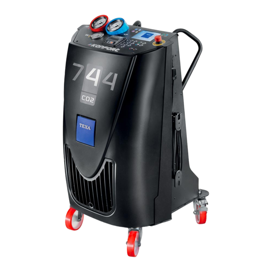
Page 20: Konfort 744 Recharging Stations
5 KONFORT 744 RECHARGING STATIONS The KONFORT 744 charging stations are intended for the maintenance of A/C systems that use carbon dioxide as refrigerant. The KONFORT 744 stations are high performance devices capable of carrying out the following operations in complete safety: system discharge, vacuum, oil injection, UV dye injection, system charge and leak checks on A/C systems. - Page 21 MAIN FEATURES • R744 compatible • High visibility TFT display • Pressure gauge assembly Cl. 1.6 • Double stage vacuum pump • 2.5 mm service pipes • Charging precision ± 10 g • Anti-contamination airtight oil bottles (patent pending) • High-precision oil injection •...
-
Page 22: Description
6 DESCRIPTION This chapter describes the general features of the charging stations. The images that follow show the charging station without the external refrigerant tank. The installation of the external tank is illustrated in a specific chapter. 6.1 Front view 1. -
Page 23: Top Panel
6.1.1 Top panel 1. TK - Refrigerant tank pressure gauge 2. HP - High-pressure gauge 3. LP - Low-pressure gauge 4. High visibility TFT colour display 5. UPG LED - software upgrade 6. BLUE Bluetooth communication 7. Thermal printer 8. Control keypad 9. -
Page 24: Rear View
6.3 Rear view 1. SD slot 2. Refrigerant tank coupler 3. Refrigerant tank anti-shift lock 4. OIL bottle status LED 5. OIL PAG air-tight bottle for specific oil 6. Refrigerant tank housing 7. FORMING GAS KIT coupler 8. Scale 9. Caster wheel with brakes 10.CO2 sensor 11.Refrigerant tank anti-shift lock 12.UV bottle status LED... -
Page 25: Containers
6.3.1 Containers 1. Bottle unlocking handle* 2. Cup fastening ring 3. Cup 4. Tank** 5. Tank cap 6. Pneumatic connection 7. Electronic connector (*) The colour of the unlocking handle indicates what the bottle must be used for. (**) not present in the DRAIN bottle The colours correspond to the following uses: •... -
Page 26: Installation
7 INSTALLATION This chapter describes the procedures required in order to install the device properly. The installation must be performed by qualified personnel only, carefully following the instructions provided in this manual. The device is provided with the following: • Technical Manual: contains the description of the device, user instructions to guarantee a correct use and correct maintenance. -
Page 27: Setting Up Before Using
8 SETTING UP BEFORE USING This chapter describes the maintenance operations required for setting up the equipment. 8.1 Scale Locking/unlocking The equipment is fitted with a locking system for the electronic refrigerant scale. The refrigerant tank is locked by the specific anti-shift locks located on the rear side of the equipment. - Page 28 Use tanks with pickup pumps only. Make sure the tank's valve is closed before proceeding with the operations indicated below. Be careful while moving the tank, especially when lifting it and placing it in its housing. If the operation is difficult (for example because the tank is heavy), ask for the help of other authorised personnel.
- Page 29 Press until selecting ADDITIONAL FUNCTIONS. Press Press until selecting TANK CHANGE. Press Make sure the tank's valve is closed. Press...
- Page 30 This step concerns replacing a tank, therefore it must be skipped. Press Place the tank in its housing. Press Apply the band heater's magnets to the tank so that the heater is well taut and the band touches the interested surface uniformly.
- Page 31 Remove the refrigerant tank hose from its resting support. Connect the refrigerant hose to the tank. Press Remove the sample weight from its housing. Place the sample weight on the tank. Press Enter the required data. Press...
- Page 32 Remove the sample weight from the tank. Put the sample weight back into its housing. Press Open the tank's valve. Press Enter the required data. Press...
-
Page 33: Moving The Device
Press 8.3 Moving the Device The device has been specifically researched and designed to lower the centre of mass; to do so the heavier components have been placed on the bottom, nonetheless it wasn't possible to completely eliminate the risk of overturning. The equipment must be moved on its own wheels. -
Page 34: Connection To The Power Mains
8.5 Connection to the Power Mains The device must be connected to the mains via the specific supply cable; respect the applicable voltage, frequency and power values. The voltage, frequency, and power values that can be applied can be found on the tag located near the main switch. -
Page 35: How To Fill The Bottles
2. Place the paper roll into the specific compartment. 3. Close the compartment pressing lightly on the cover and leaving a slip of paper sticking out. Press to make sure the paper has been inserted correctly. 5. Repeat the operations indicated above if the paper does not come out. 8.8 How to Fill the Bottles You must fill the oil and UV tracer bottles before use. - Page 36 You must set the software's display language. This operation must be carried out when the equipment is started for the first time. You may change the language selected at any time by following the instructions provided in this chapter. The following procedure uses as examples screens displayed by the charging stations that are equipped with a TFT colour display.
- Page 37 Press until reaching the item that corresponds to the desired language. Press The language is set.
-
Page 38: Start-Up
9 START-UP This chapter describes the operations required in order to start up the device. 9.1 Switching on To start up the device, set the main switch in the I (ON) position. 9.2 Activation The device includes a demo mode (Demo). The device can be used in Demo mode for a maximum cycle of 15 power on- power offs. -
Page 39: User Instructions
10 User Instructions This chapter provides various general instructions on how to use the device. For further information consult the software's Operating Manual. 10.1 How to Connect to the Vehicle Air Conditioning System In order to carry out A/C system recharging operations you are required to connect the device to the vehicle. -
Page 40: How To Use The Software
(CO2) has returned to normal. 10.5 How to Use the Software The software installed in the KONFORT 744 charging stations allows you to launch all the functions needed for recharging and checking the vehicle's A/C system. -
Page 41: Printer
These keys allow you to enter the alphanumeric values required to carry NUMERIC KEYPAD out the recharging operations and data related to the client and the company. The software provides on-screen instructions to help the operator to carry out the various operations and warns the operator if any error occurs during the individual phases. - Page 42 • company data • vehicle data • client data • operations carried out The data relative to the company, vehicle and the client can be entered using the numeric keypad. For further information consult the software's Operating Manual.
-
Page 43: Stop
11 STOP This chapter describes the operations required in order to stop the equipment. Do not switch off the equipment by disconnecting the power cable from the socket. Before switching off the equipment, using the specific pressure gauges, make sure the service pipes are not under pressure and eventually depressurise them through the specific software function. -
Page 44: Updating
12 UPDATING This chapter describes the operations needed to update the equipment's operating system. The update takes place through the SDCARD. You must have a PC with a USB port and an active Internet connection available. Proceed as follows: 1. Turn off the device. 2. -
Page 45: Maintenance And Cleaning
Any maintenance operation on the equipment must be carried out only by personnel authorised by TEXA S.p.A. Carefully follow the instructions provided in this manual. Only use original spare parts or approved by TEXA S.p.A. For more information contact the post-sales assistance service. 13.1 Ordinary Maintenance Scheduled maintenance is made up of a series of operations that must be carried out periodically. -
Page 46: How To Replace The Vaccum Pump Oil
13.1.1 How to Replace the Vaccum Pump Oil The oil in the vacuum pump must be replaced when you are prompted to do so by the device. You must carefully read and understand this Operating Manual in order to perform the provided instructions correctly. 1. - Page 47 PART SUBJECT TO WEAR CHECK Make sure there are no cuts, scratches Service hoses or bulges. Make sure there are no signs of wear and that the hoses do not harden during use. Quick fittings Make sure the service hoses are connected properly.
-
Page 48: Disposal
14 DISPOSAL Below you will find information on how to properly dispose of the device. 14.1 How to Dispose of the Device Take the device to a waste disposal centre. For more information regarding the disposal consult the pamplet provided with the device. 14.2 How to Dispose of the Recycled Materials The oils removed from the systems must be taken to used oil collection centres. -
Page 49: Technical Features
15 TECHNICAL FEATURES Builder TEXA S.p.A. Model K744 Coolant R744 (carbon dioxide, CO2) Electronic refrigerant scale (Precise) ± 5 Electronic oil and UV tracer scales ± 1 (Resolution) [g] High pressure gauge [mm] Ø 80 Low pressure gauge [mm] Ø 80 TK pressure gauge (external tank) Ø... - Page 50 Current draw [A]...
-
Page 51: Legal Notices
16 LEGAL NOTICES TEXA S.p.A. Via 1 Maggio, 9 - 31050 Monastier di Treviso - ITALY Cod. Fisc. - No. of Companies' Register of Treviso - Part. IVA: 02413550266 Single member company and subject to management and co-ordination of Opera Holding S.r.l.
Need help?
Do you have a question about the KONFORT 744 and is the answer not in the manual?
Questions and answers