
Related Manuals for LONGER Orange10


Summary of Contents for LONGER Orange10
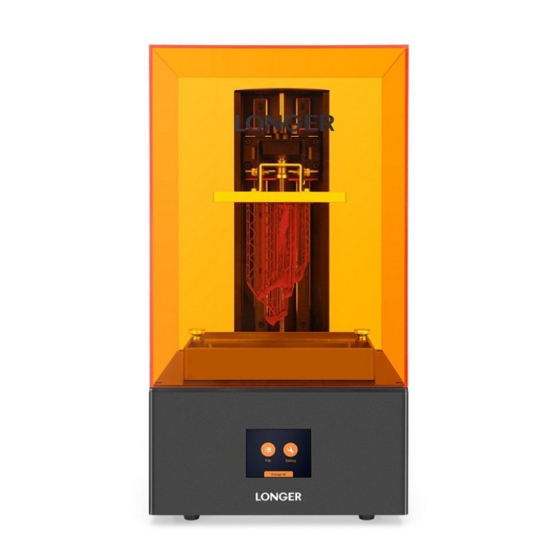
- Page 1 LONGER Technology Orange10 LCD 3D Printer User Manual Version1.0 www.longer3d.com info@longer3d.com...
-
Page 2: Table Of Contents
Contents 1. Introduction..........................1 2. Specifications......................... 2 3. Product Overview........................3 3.1 The 3D printer description....................3 3.2 The accessory box......................4 4. Active Your 3D Printer......................4 5 Touch Screen Description.......................5 5.1 Main Menu........................5 5.2 File.............................5 5.3 Job ............................. 7 5.4 Setting.......................... -
Page 3: Introduction
1. Introduction This user manual is provided to the operator with necessary and detailed instructions for safe and correct operation, software, maintenance, troubleshooting of Orange10 LCD 3D printer. This manual document must be read carefully before installation and operation of the printer. -
Page 4: Specifications
2. Specifications Equipment Model Orange10 Printing Technology LCD stereolithography Build Size 9855140mm Layer Thickness 0.02-0.10mm LCD Resolution 854480 pixel, 115μm Z axis Resolution 0.625μm Build Speed 30mm/h ((100μm layer thickness)) Material Photopolymer Resin Light Source UV LED 405nm Software LONGER... -
Page 5: Product Overview
3. Product Overview 3.1 The 3D printer description Hood Z aix Building platform fixed screw Leveling fixed screw Building platform Vat fixed screw Touch screen TF card Thermal via Power port Switch www.longer3d.com info@longer3d.com... -
Page 6: The Accessory Box
3.2 The accessory box TF Card1 Power Adapter1 Filtering Funnel2 Latex Gloves2 Photopolymer Resin Scraper1 Card5 Release Film1 250mL1 ● Screw Kits1 ● Hexagon Wrench 1.5mm ● Hexagon Wrench 2mm ● Hexagon Wrench 2.5mm ● Hexagon Wrench 3mm ● Hexagon Wrench 4mm 4. -
Page 7: Touch Screen Description
5 Touch Screen Description 5.1 Main Menu Home: enter into tools interface which contains “File” and “Setting”. File: the list of printing files, and selection of file to print. Setting: move the Z axis; check LCD and LED; information of the printer. - Page 8 Back to home page. Confirm the start printing. Cancel the printing operation. Select the file to print from the list, the selected file will be surrounded by red frame. Click the START, a pop-up window appears to confirm the operation. Choose to start the printing, or select NO to cancel the printing.
-
Page 9: Job
5.3 Job Pausing Paused Printing process of current layer and total layers. Remaining time to printing completion. Elapsed time from start printing. Real-time temperature of LED PCB. Pause the printing job. The status will change to pausing when start to pause, and switch to paused after the current layer is printed over. -
Page 10: Setting
Real-time printing status. Confirm the stop printing. Cancel the stop operation. 5.4 Setting 1) Move: move the Z axis. Move up the Z axis. Move down the Z axis. Move the Z axis by 1mm (change move distance by clicking the button). -
Page 11: More
Move the Z axis to the home position. Stop the motion immediately. Back to home page. 2) LED Turn on the LED light and a white picture will be showed to confirm that the LCD and LED are ok (make sure there is no resin in the vat, otherwise the resin will be cured). -
Page 12: Leveling
Printer Model: the model number of the printer. Temperature: the temperature of LED. Serial Number: the ID of the printer. Firmware Version: the version of printer’s firmware. 5.6 Leveling 1) Turn on the printer, move up the Z axis, take out the building plate, install it as the picture as shown below. - Page 13 3) Loosen the “vat fixed screw”, take down the resin vat, and put a pieces of A4 paper on the LCD screen. Move down the building platform to home position, press and hold it, then fasten the leveling fixed screws diagonally. 4) Drag the A4 paper and feel the force of dragging the paper.
-
Page 14: Software User Manual
Pull Pull 5) Move up the building platform when the adjustment of home position is finished. Then, install the resin vat, tighten the vat fixed screw, pour into the resin. It needs to add resin manually if the volume of model is bigger than resin left in the vat during printing. 6 Software User Manual 6.1 PC Requirements Windows 7/8/10, 64-bit;... - Page 15 C:\Program File (86)\longerware), the installation will begin. To complete the installation by clicking “Finish”, the slice software will run and create a shortcut on the desktop. www.longer3d.com info@longer3d.com...
-
Page 16: Printing Procedure
6.4 Printing Procedure 1) Open the stl model. 2) Edit the model, such as translate, rotate, scale and clone. 3) Fix the error. 4) Generate support if necessary. 5) Slice the model. 6) Generate and save the printing job file to TF card. 7) Connect to the TF card to printer. -
Page 17: Main Menu
6.5 main menu Menu Bar Tools Bar ● Open View Bar ● Open ● Delete ● Edit ● Fix ● Support Building Volume ● Slice ● Print Building Platform Model Open: load the stl model. Menu Delete: delete the selected model. Open: load the stl model. -
Page 18: Open
Support: generate and edit the support. Slice: slice the model. Print: set the printing parameter, generate and save the printing job. Top view Bottom view Left view Right view View Isometric view Printer Setting: select the kind of printer. Minimize the window. Maximize the window. -
Page 19: Edit
Click Open icon to load stl model. It needs to open files separately to load different models. Select the model, three submenus appear under the open icon, such as translate, rotate, scale, and an edit dialog shows in the left bottom (The model presents blue when selected, otherwise presents grey). -
Page 20: Fix
Reset: recover to the original status. Maximize: the model change to maximum size within building volume. 6.8 Fix Fix: check out the error(s) of the selected model, such as holes, non-manifold, inverted normal, and click Fix to auto-repair the error(s). If there are some errors that cannot be repaired by software, it needs use other professional software to fix, such as Netfabb, Magics,... -
Page 21: Support
6.9 Support ② ③ ① Support: Select the model, click support icon, edit the parameters, click Generate icon. Generate: generate support for the selected model. Edit: edit the support parameters, the support positions are showed by purple point. Add support by left click at desired position of the model;... - Page 22 support position Shaft Diameter: the diameter of support column, the larger value, the stronger support, but more difficult to remove. The suggested value is about 0.8. Lift Distance: the distance between the model and building platform is lifted by generating support. The suggested value is between 0 to 3mm.
-
Page 23: Slice
6.10 Slice ④ ② ③ ① Thickness: the current layer thickness of printing model. Thickness Setting: set the layer thickness, the suggested value is between 20 to 100μm. Advanced Setting: set the layer number of base plate to strong the adhesion between model and building platform, the height of base is about 0.3mm, so the layer number is set to 6 when the layer thickness... -
Page 24: Generating Job File
image can be previewed in the window by dragging the block in the bottom or input the number of layer in the blank. 6.11 Generating Job File Choose the same material type as printing material from material list; click Start to generate a printing job file with a file suffix of lgt. - Page 25 50μm layer thickness. But it needs to add the exposure time, such as 8000 to 12000ms, for the model with fine size. Bottom Time: the exposure time for the bottom layers. The longer time, the stronger adhesion between model and building platform. www.longer3d.com...
-
Page 26: Post-Processing
The default time is 80000ms. Stable Time: the time between stop motion of Z axis and LCD projection. The default time is 1000ms Bottom Height: the height that is over cured for increasing the adhesion between model and building platform. The default height is 0.3mm. - Page 27 building platform and loose the fixed screw, take out the platform carefully. Put the building platform on a plastic paper to prevent resin from sprinkling on the desktop. Remove the model by metal scrapper with attention. Pour the ethanol with 95vol% concentration into a container, immerse the model into ethanol and shake it gently, then swash the model with clear ethanol for better cleaning.
-
Page 28: Faq
7. FAQ the graphics driver is old update the graphics driver to the latest version screen slice the graphics card of computer is change to a high performance graphics card, such as discrete graphics card software is black too old building platform loosen tighten the building platform home position too high... -
Page 29: Attentions And Maintenance
8. Attentions and Maintenance 1) Must wear latex gloves each operation. 2) The photopolymer resin must be kept out reach of children. 3) Before each printing, make sure that there is no solid residue on the platform or in the resin vat. 4) Do not use sharp object to scrape the release film of resin vat. -
Page 30: Printing Cases
9. Printing Cases Printing parameters: Exposure time-6000ms, bottom time-80000ms Layer thickness-50μm, Bottom height-0.3mm Lift Distance1-2mm, Lift Speed1-48mm Lift Distance2-2mm, Lift Speed2-300mm Notes: The model is hollowed to decrease resin consumption, and punched at the bottom to let resin flow out from model. The wall thickness of hollow part is about 1.8-2.0mm.
Need help?
Do you have a question about the Orange10 and is the answer not in the manual?
Questions and answers