Table of Contents
Advertisement
Quick Links
Advertisement
Table of Contents

Subscribe to Our Youtube Channel
Related Manuals for Buchi SpeedExtractor E-914


Summary of Contents for Buchi SpeedExtractor E-914
- Page 1 SpeedExtractor E-916 / E-914 Operation Manual 093218F en...
- Page 2 E-Mail: quality@buchi.com BUCHI reserves the right to make changes to the manual as deemed necessary in the light of experience; espe- cially in respect to structure, illustrations and technical detail. This manual is copyright. Information from it may not be reproduced, distributed, or used for competitive purpos- es, nor made available to third parties.
-
Page 3: Table Of Contents
Table of contents Table of contents About this manual ................................5 Reference documents ............................5 Trademarks ................................5 Abbreviations ................................. 6 Safety ...................................... 7 User qualification ..............................7 Proper use ................................7 Improper use ................................7 Safety warnings and safety signs used in this manual ................8 Product safety ..............................10 2.5.1 General hazards .............................10 2.5.2 Warning labels on housing and assemblies ................11... - Page 4 Table of contents Operation ....................................35 Method development ............................35 Preparing the instrument ..........................36 6.2.1 Solvent reservoir ............................36 6.2.2 Modifying the SOLVENT LIST ......................37 6.2.3 Preheating the instrument ........................38 6.2.4 Activating/deactivating positions ....................39 6.2.5 Leak test ..............................40 6.2.6 Flushing the instrument ........................43 6.2.7 Activating the EcoMode ........................44 Preparing the sample ............................45 6.3.1 Sample preparation ..........................45...
- Page 5 Store the manual in the immediate vicinity of the instrument, so that it can be consulted at any time. No technical modifications may be made to the instrument without the prior written agreement of BUCHI. Unau- thorized modifications may affect the system safety or result in accidents.
-
Page 6: About This Manual
NOTE The symbols pertaining to safety are explained in chapter 2. Reference documents For information on complementary BUCHI devices, please refer to the corresponding manuals: Complementary devices Multivapor P-6 / P-12, Operation Manual Vacuum Controller, Operation Manual Vacuum Pump, Operation Manual... -
Page 7: Abbreviations
1 About this manual Abbreviations Process-related Accelerated Solvent Extraction Pressurized Solvent Extraction Materials and chemicals Combination of tetrafluoroethylene and hexafluoropropylene FFPM Perfluoro caoutchouc PTFE Polytetrafluoroethylene Polyoxymethylene (commercialized as Delrin® by DuPont) PEEK Polyether ether ketone Tetrahydrofurane Miscellaneous firm ware quantity Temperature difference Pressure difference SpeedExtractor E-916 / E-914 Operation Manual... -
Page 8: Safety
Use in conjunction with solvents that have a low self ignition point or contain peroxides, such as diethyl ether or THF. • Use of cells, seals, hoses, and tubes other than the originals from BUCHI. SpeedExtractor E-916 / E-914 Operation Manual... -
Page 9: Safety Warnings And Safety Signs Used In This Manual
2 Safety Safety warnings and safety signs used in this manual DANGER, WARNING, CAUTION and NOTICE are standardized signal words for identifying levels of hazard seriousness of risks related to personal injury and property damage. All signal words, which are related to personal injury are accompanied by the general safety sign. - Page 10 2 Safety Symbol Meaning Fire hazard Hot item, hot surface Device damage Inhalation of substances Chemical burns by corrosives Wear laboratory coat Wear protective goggles Wear protective gloves Heavy weight, lifting requires more than one person Additional user information Paragraphs starting with Note transport helpful information for working with the device/software or its supplementary.
-
Page 11: Product Safety
2 Safety Product safety The SpeedExtractor has been designed and built in accordance with current state-of-the-art technol- ogy. Safety warnings in this manual (as described in section 2.4) serve to make the user alert to and avoid hazardous situations emanating from residual dangers by giving appropriate counter measures. However, risks to users, property and the environment can arise when the instrument is damaged, used carelessly or improperly. -
Page 12: Warning Labels On Housing And Assemblies
2 Safety NOTICE Risk of instrument damage by liquids or mechanical shocks. • Do not spill liquids over the instrument or its components • Do not move the instrument when it is loaded with sample liquid • Do not drop the instrument or its components •... -
Page 13: Built-In Safety Elements And Measures
2 Safety 2.5.4 Built-in safety elements and measures • The heating element is equipped with overtemperature protection which is activated at 260 °C ±10 °C. • The pressure parts are protected by a mechanical pressure control valve which is activated at 200 bar ±20 bar. • To start a program at least one extraction position must be activated. -
Page 14: General Safety Rules
Modifications to the instrument are only permitted after prior consultation and with the written approval of the manufacturer. Modifications and upgrades shall only be carried out by an authorized BUCHI technical engineer. The manufacturer will decline any claim resulting from unauthorized modifications. - Page 15 2 Safety SpeedExtractor E-916 / E-914 Operation Manual...
-
Page 16: Technical Data
6 positions, E-914: 4 positions), the type of solvent mixer (2 ports or 4 ports), and the size of the extraction cells (E-916: 10 – 40 mL, E-914: 10 – 120 mL). The SpeedExtractor E-914 is available with and without pedes- tal (the pedestal allows to accommodate large volume collection recipients). - Page 17 3 Technical data Number of positions E-914: 4 positions E-914: 4 positions mounted on pedestal E-916: 6 positions Size of extraction cells 10 mL (E-916 only) 20 mL (E-916 only) 40 mL 80 mL (E-914 only) 120 mL (E-914 only) Number of solvent ports Ports Ports List of loose parts Position Item...
- Page 18 3 Technical data List of loose parts Position Item Universal Order no. E-914 Order no. E-916 Spanner wrench 1/4" 053204 Spanner wrench 8/10 mm 053608 Torx screwdriver TX20 053668 USB cable 2.0 A-B, 4.5 m 049226 Plug screws 053209 Metal frit 049568 053671 053669 Cup seals, top...
-
Page 19: Materials Used
3 Technical data Materials used Materials used Component Material designation Housing SpeedExtractor Stainless steel Lines to pump Solvent valve PEEK, FFPM Mixer PEEK, FFPM Media valve PEEK, PTFE Lines to and from heating block Stainless steel Pressure gauges Stainless steel Position valves Stainless steel, PTFE Outlet valves... - Page 20 3 Technical data Technical data of the SpeedExtractor Description Technical data 50 – 150 bar Pressure range ±5 bar Pressure accuracy 6 – 10 bar Primary pressure nitrogen connection 1 – 50 mL/min Flow rate pump Precision flow rate ±2 % ±2 % (±5 % for isopropanol) Precision mixer Extraction cell size E-916: 10, 20, 40 mL;...
- Page 21 3 Technical data SpeedExtractor E-916 / E-914 Operation Manual...
-
Page 22: Description Of Function
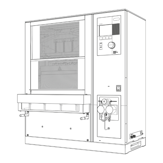
4 Description of function Description of function This chapter explains the basic principle of the SpeedExtractor E-916 / E-914 and provides a functional description of the assemblies. Functional principle The SpeedExtractor E-916 / E-914 is an automated instrument for parallel extraction of primarily organic compounds from a variety of solid or semi-solid samples. - Page 23 4 Description of function a Main power switch The instrument is protected by a 14 A (240 V) circuit breaker. The main fuse button at the rear of the instrument must be pushed in. b Solvent reservoir The maximum possible number of solvent bottles depends on the type of mixer. With the 2-port mixer up to 2 different solvents, with the 4-port mixer up to 4 different solvents can be connected allowing any user-defined solvent ratios.
-
Page 24: Overview Of The Extraction Process
4 Description of function Overview of the extraction process A complete extraction process involves the following phases: Phase 1: Preparation • Creating an extraction method (see section 6.2.3). • Preparing the instrument for operation. This involves filling the solvent reservoirs and preheating the instrument to the temperature of operation (equilibration), see section 6.2.3. -
Page 25: Schematic Representation Of The Process
4 Description of function cells is absolutely mandatory. Placing the cells in the cold instrument followed by heating up the closed system might damage the cup seals. It is therefore crucial to note that the temperature of the instrument must not be changed once the system is closed. The instrument is ready once the set temperature is reached (which is shown in the main display) and the extraction process is started by pressing START. -
Page 26: Controls And Connections
4 Description of function a Solvent reservoirs (3 and 4 optional) b Nitrogen tank c Solvent valves d Mixer e Pump f Media valve g Divider h Overpressure valve i Position valves j Pressure sensors k Upper cup seals l Extraction cells m Lower cup seals n Cooling units o Outlet valve... -
Page 27: Main Displays Of The Instrument
4 Description of function NOTE The START and STOP buttons are used only for the extraction method but have no effect on func- tions such as preheat, leak test, or flush. All functions apart from extractions are initiated by function buttons b. - Page 28 4 Description of function a Current extraction cycle/total extraction cycles b Name of the current extraction method. When the name is crossed out (DEFAULT), the current method has been changed and not yet saved (see section 6.4.3). c Total remaining time of the extraction process. d Status: PREHEAT, READY, all methods steps, PAUSE, and ABORT.
- Page 29 4 Description of function a Performing a LEAK TEST (see section 6.2.5). b Flushing the lines with solvent in collection vials or a waste bottle. Parameters like time, flow rate and solvent mixtures are defined in submenus (see section 6.2.6). c Defining instrument settings like language, contrast of the dis- play, acoustic signals, preheat demand when the instrument is turned on.
-
Page 30: General Information On Buttons
4 Description of function 4.5.3 General information on buttons The following control buttons are available in the software for navigation and input configuration: Open the extraction menu Open the menu functions like leak test, instrument settings etc. Open the status menu Get back to the previous screen Get on to the next screen or entries of a screen Leave the current screen and get back to the main display... -
Page 31: Rear Connections
4 Description of function 4.5.4 Rear connections a Mains supply b Main fuse c RS232 port d USB 2.0 port e Exhaust outlet for purging with nitrogen, discharge and tightness test f Waste outlet for flushing with solvent or collecting extracts 4.5.5 Side connections a Nitrogen inlet... -
Page 32: Putting Into Operation
5 Putting into operation Putting into operation This chapter describes the installation of the SpeedExtractor and gives instructions on initial start-up. NOTE Inspect the instrument for damages during unpacking. If necessary, prepare a status report imme- diately to inform the postal company, railway company or transport company. Keep the original packaging for future transport. -
Page 33: Electrical Connections
5 Putting into operation NOTE The instrument does not have to be operated under a fume hood but the exhaust must lead into some kind of ventilation device. Never hold the instrument on the collection rack or pump heads to move the instrument. Always use the handles on the side. -
Page 34: Gas And Solvent Connections
5 Putting into operation Gas and solvent connections • Connect nitrogen gas by means of the provided hose. The corresponding joint contains a quick- lock mechanism. The nitrogen gas connection is located on the right hand side panel. The required pressure range is 6 – 10 bar. This pressure has to be set at the external pressure reduction valve. -
Page 35: Dehydration
5 Putting into operation Dehydration NOTE At initial start-up or after a long period of no use (>1 month), the instrument should be dehydrated for proper operation. To do so, heat up the instrument to 100°C for 1 hour (heater open, no cells). Proceed as described in section 6.3.2. -
Page 36: Operation
For further information regarding the vial change, see section 6.4.3. Further information about how to optimize the extraction process is given in section 6.4.7. BUCHI's SpeedExtractor Application booklet and Application notes give detailed information about method de- velopment and method parameters for a waste range of applications. -
Page 37: Preparing The Instrument
Do not use solvents with an self ignition point of 40 to 220 °C. Particularly, do not use the following solvents with the SpeedExtractor. If there is any question about solvent suitability, contact BUCHI. Solvents NOT being compatible with the process... -
Page 38: Modifying The Solvent List
6 Operation Never use technical grade solvent. It is strongly recommended to use particle free solvents such as p.a. quality or HPLC grade solvent to guarantee proper operation of the valves, filters and frits. Filling the solvent reservoir: To prevent air from being drawn though the lines, insert the inlet line (approx. -
Page 39: Preheating The Instrument
6 Operation Adding a new solvent: • To add new solvents to the list go to an empty posi- tion (e.g. no. 11) and press EDIT. The editing display is now empty. You can create your own names now using the selection knob. For example: An extrac- tion is performed with chlorobenzene which does not belong to the standard list. -
Page 40: Activating/Deactivating Positions
6 Operation Setting the preheat temperature: • Go to EXTRACTION PREHEAT to open the preheat submenu. CURRENT METHOD indicates the temperature setting of the current method. Use COPY to copy this value in the preheat entry to heat up the instrument to the temperature for the next run. -
Page 41: Leak Test
6 Operation Activate all positions together: • Open EXTRACTION OCCUPIED POSITIONS. Confirm “Occupy all positions?” with YES. The main display shows all activated positions as numbered cylinders. Deactivate positions: • To activate only the four middle positions, activate all positions first and then deactivate the positions 1 and 6. - Page 42 6 Operation Method-based leak test Open the method: • Go to EXTRACTION OPEN METHOD and select the requested method (e.g. PAH-01) and confirm with OK. The name of the selected method now appears in the main display. Copy the parameters into the leak test: •...
- Page 43 6 Operation Reference setting for a standardized leak test Description Value Temperature 100 °C Pressure 100 bar Solvent ethanol Hold time 4 min Extraction cell all volumes Expansion element, sand Expansion element 2–120 m L (refer to chapter 1 0) or sand • Set the reference settings: Open MENU ...
-
Page 44: Flushing The Instrument
This second leak test helps to identify the faulty valve. For exchange of a defective position valve, please contact BUCHI Service. • The check valves of the pump are clogged due to impurities clean the check valves (see sec- tion 8.1.5) -
Page 45: Activating The Ecomode
6 Operation mode when positions are deactivated. This allows a fast and efficient flushing when using a reduced number of positions. Flush into waste: • Open MENU FLUSH. Set the time to flush with solvent. FLUSH INTO makes it possible to choose between waste or vial. -
Page 46: Preparing The Sample
For critical samples it is therefore recommended to use a smaller cooling unit instead (P/N 053682). Exchange of the cooling unit, however, requires an authorized service technician. Please contact BUCHI or your local dealer. SpeedExtractor E-916 / E-914 Operation Manual... -
Page 47: Extraction Cell Selection
6.4.2), as well as the amount of solvent used for the method. As • 40 mL P/N 051235 the cell is filled with solvent during an extraction process, larger cells, SpeedExtractor E-914 or only partially filled cells require more solvent. However, the same • 10 mL 11067988* method might require slight modifications if performed with different •... - Page 48 6 Operation Alternatively, use a paper or glass fiber thimble to fill in your sample. The thimbles are recommended for polymers and plastics (samples with tendency to melt during the extraction process) and sticky samples, when not mixed with sand or diatomaceous earth. They are specially recommended for the method development of the mentioned sample types.
- Page 49 6 Operation C Keep the sealing surfaces clean Insert the upper cellulose g (P/N 049572 for E-916, P/N 051249 for E-914) or glass fiber filter (P/N 11057189 for E-916, P/N 11057190 for E-914) carefully uniformly into the cell using the plunger h. The top glass fiber filters are recommended for trace and ultra-trace analysis.
-
Page 50: Extraction Process
6 Operation Extraction process Each extraction procedure occurs according to a set of predefined operating parameters such as pressure, temperature, flow rates etc. which are all part of the extraction method. The SpeedExtractor can store up to 100 methods. The optional PC software SpeedExtractor Record allows to create and manage an unlimited number of methods. -
Page 51: Stages Of An Extraction Cycle
6 Operation The heating block is fixed on movable guide rails. This allows the operator to push the heating block to the back to get easy access to the cup seals (for inspection or exchange) and to pull it out to load the extraction cells. -
Page 52: Creating New Methods
6 Operation to 1/3 and 2/3 of the final pressure. The HEAT UP time is defined as the time during which the pressure remains at 1/3 of the total pressure. A further prerequisite is that the temperature of the heating block reached its equilibrium. It is a method-dependent intrinsic parameter which depends mostly on the size of the extraction cell and is therefore not adjustable by the operator. - Page 53 6 Operation Specify the vial volume: • Specification of the volume of the collection bottle is an important safety feature, since it alerts the oper- ator if there is a conflict with the total volume used for the subsequently defined extraction volume. The volumes of the most frequently used bottles (60 mL, 150 mL, 220 mL and 240 mL) are predefined.
- Page 54 6 Operation Define the cycles: • Specify the number of cycles and go to the CYCLES submenu. The CYCLES submenu contains all cycles including their operating parameters such as HEAT- UP, HOLD and DISCHARGE time. There are only as many cycles shown as defined in NUMBER OF CYCLES.
-
Page 55: Summary Of Operating Parameters
Size of the collection bottle. There are different vials avail- 60, 150, 220, 240 mL, able from BUCHI: flat bottom narrow neck vials (60, 240 mL) / unspecified, waste round bottom open neck vials (220 m L) / Analyst vials (150 m L) (default: 240 mL) - Page 56 6 Operation Operation parameters Parameter Function Value range TYPE Type of solvent in solvent reservoir 1 – 2 or 1 – 4 depending on the list of 20 solvents instrument configuration. (default: 10 solvents) RATIO Percentage of solvent 1 – 2 or 1 – 4 used to create the extraction 1 –...
-
Page 57: Example Of An Extraction Method
6 Operation 6.4.5 Example of an extraction method Example: Extraction of 6×5 g sample in 10 mL extraction cells with acetone 50 % and DCM 50 %, 3×5 min at 80 °C and 100 bar. Procedure: • Connect the solvent reservoirs to the corre- sponding ports: a: acetone, b: DCM •... -
Page 58: Optimize A Process
0-1 bar. For more detailed information about method development and optimization, please consider BUCHI's SpeedExtractor Application booklet and BUCHI's Application and Technical Notes. Please contact your sales person or BUCHI for these documents. -
Page 59: Start, Pause, Stop And Abort Extraction
6 Operation 6.4.8 Start, pause, stop and abort extraction Use the green START and the red STOP buttons to start, pause, abort, or interrupt an extraction pro- cess. These buttons are only applicable to the extraction process. All other procedures such as flush or preheat are controlled by the function buttons (see also section 4.5.1). -
Page 60: Creating A Report (Optional)
6 Operation Cleaning the seals • If necessary, rinse the seals with organic solvent (e.g. ethanol) with the help of beaker. Always visually inspect the seals for dust, sand or scratches. NOTE Never clean the cup seals with a wet towel or wipe. Any kind of residue might cause a leak and/or reduce the lifetime of the cup seals. - Page 61 6 Operation SpeedExtractor E-916 / E-914 Operation Manual...
-
Page 62: Maintenance
7 Maintenance Maintenance This chapter provides instructions on all required maintenance to keep the instrument in good working condition. WARNING Death or serious burns by electric current at cleaning. • Switch off the instrument • Disconnect the power cord and prevent unintentional restart •... -
Page 63: Periodic Maintenance
7 Maintenance Periodic maintenance 7.2.1 Sealing system The condition of the cup seals is crucial for the tight- ness of the system. Any kind of contamination on either the sealing surface of the extraction cell or the seal itself significantly reduces the lifetime of the seals. Therefore, always proceed as described in section 6.3.3 to fill the cell. -
Page 64: Tube Connections And Needles
Visually examine the tube connections on a regular basis. All tubes which are accessible without open- ing the housing can easily be exchanged by the operator. For all other lines please contact your local BUCHI representative. Solvent reservoir connections The FEP tubes a (OD 1/8”, ID 1/16”) are fixed with green ferrules b and fittings c (1/4 UNF-28, D 1/8”). - Page 65 7 Maintenance Exhaust connections A good indication for clogged needles or EXHAUST lines is a reproducible residual pressure of approx. 1 – 2 bar after each run. In this case the lift does not open and an error message appears (see sec- tion 8.1.2).
-
Page 66: Septum
7 Maintenance Needles The needles need to be replaced regularly (i.e. at least after every 6 months) to reduce the risk of clogging by particles of the septa or when they are bent. To do so, remove the covers a and b. Unscrew the needles with the wrench P/N 053204 and pull them out from the bottom. -
Page 67: Pump Maintenance
7 Maintenance Pump maintenance Pump designations a Mixer outlet line b Pump inlet lines (left, right identical) c Pump heads d Pump outlet capillary left e Pump outlet capillary right f By-pass valve 7.3.1 Connections FEP tubings Use FEP tubing OD 1/8”, ID 1/16” for the mixer outlet and pump inlet lines. -
Page 68: Back Washing
7 Maintenance 7.3.2 Back washing Back washing is an important maintenance procedure when not only pure and filtered solvents are used such as for example buffer solutions. The pump consists of two heads for alternate pump- ing and purging. They are both equipped with a Luer cone in the upper part, into which a plastic syringe (P/N 034882) can be inserted as shown in the pic- ture. - Page 69 7 Maintenance SpeedExtractor E-916 / E-914 Operation Manual...
-
Page 70: Troubleshooting
“Remedy”. More complicated malfunctions or errors are usually handled by a BUCHI technical engineer who has access to the official service manuals. In this case, please contact your local BUCHI customer service agent. - Page 71 60 min preheating time. reached. If this occurs frequently, contact BUCHI customer service. The heater may have a problem. Error 7 Method not complete. Parameters of the extraction Complete the extraction method...
- Page 72 Malfunction Display information Possible cause Remedy Error 21 No power consumption of vial The motor is either disconnected Contact BUCHI customer service. lift motor. Please refer to user or damaged. manual. Errors related to pressure sensors or pressure in general. Error 22 Calibration of pressure sensor A pressure sensor is defective.
- Page 73 8 Troubleshooting General malfunctions and their remedy Malfunction Display information Possible cause Remedy Error 51 Pump pressure too high. Please During Extraction Check the state of the media, refer to user manual. position and outlet valve. Open The pump is purging against the corresponding valve(s) in the a closed system, i.e.
- Page 74 EXTRACTION EDIT METHOD SOLVENT. Contact BUCHI customer service to exchange the defective parts. Error 66 Pressure not reached. Pump The set pressure is not reached Depending on the cause proceed timeout.
-
Page 75: Handling And Resolving Blockages
A short first cycle can be helpful for samples with high concentration of analyte (e.g. fat in food samples). For more detailed information about sample preparation and method development, consider BUCHI's Application Notes, Technical Notes and the SpeedExtractor Application Book- let. Please contact your local representative or BUCHI for these documents. - Page 76 8 Troubleshooting CAUTION Risk of minor or moderate injuries by hot steam of solvent when opening the drain valve. • Use a towel or insulated gloves for protection There are three cases to distinguish depending of the pressure in the clogged position and the num- ber of clogged positions.
- Page 77 8 Troubleshooting Error 29 – 34 Position X clogged: press START to disable position or repeat to discharge Repeat START Wobble position: position Pressure released? is disabled Extraction with other Extraction with all posi- positions tions End: heater opens Error 42 A clogging occurred during extraction.
- Page 78 8 Troubleshooting Error 35 – 40 Position X clogged: press repeat to discharge or relieve the pressure manually. Repeat Control of pressure in STATUS Relieve pressure manually Error 35 – 40 Pressure released? repeat START No wobble position; position is deacti- vated.
- Page 79 8 Troubleshooting Error 41 Position X clogged: press repeat to discharge or relieve the pressure manually. Control of pressure in Repeat STATUS Relieve pressure manually of all clogged positions Error 41 Pressure released? repeat START One position is deactivated, extraction of other positions continues Error 41 No error...
-
Page 80: The Pump Is Not Aspirating Properly
8 Troubleshooting 8.1.4 The pump is not aspirating properly NOTE When the pump is running but the solvent is not aspirated check first if the right solvent port is selected (see section 6.2.6). A new pump or a pump that has been out of operation for a long time may sometimes be difficult to start. -
Page 81: Replacement Of Check Valves
8 Troubleshooting 8.1.5 Replacement of check valves The principle of a check valve is a precise ball and seat located in a casing of PEEK material with stainless steel reinforcement. By a stream of liquid the ball is pressed down to the seat, thus creating a seal. With respect to high pressures in the pump, any minute impurity stuck on the surface of the ball or the seat causes pressure fluctuation, or the pump fails to start at all. -
Page 82: Precipitation In The Outlet Lines
The alternative cooling unit (P/N 053682) must be installed by a BUCHI approved service technician. Please refer to your local dealer or BUCHI customer service. -
Page 83: Malfunctions Of The Rotating Valves
Upgrading a 2-port mixer to a 4-port mixer The SpeedExtractor E-916 / E-914 is available with a 2- or a 4-port mixer. A BUCHI-approved service technician can retrofit a 2-port configuration with a 4-port mixer (P/N 053381). Please contact the local dealer or BUCHI customer service. -
Page 84: Description Of The Service Menu
8 Troubleshooting Description of the service menu The service menu provides direct access to all technical process components such as valves, sen- sors, pump, lift and fan independent of any extraction method. It is therefore possible to switch valves, run the pump or move the lift for troubleshooting purposes. In addition instrument information is avail- able, like operating hours and version of certain components. -
Page 85: Checking The Valves
8 Troubleshooting Description of the service menu Service function Description Typically used for: Lift The lift for the heating block (cell lift) and the collection rack (vial To open the cell lift after (see 8.2.5) lift) can be moved up and down. Light barriers show the corre- manual draining of the sponding position and the used current indicates possible blockage extract in case of clogged... -
Page 86: Checking The Sensors
Go to SERVICE FUNCTIONS PUMP. Enter the flow rate us- ing the selection knob (1 – 50 mL/min). Press ON. The ACTUAL VALUE converges to the set value. If the ACTUAL VALUE remains 0, the pump is defective. Contact a BUCHI service engineer. The actual pressure is shown. -
Page 87: Inspecting The Lines (Flow Test)
8 Troubleshooting 8.2.4 Inspecting the lines (flow test) Go to SERVICE FUNCTIONS FLOW. Define the parameters using the selection knob. Press START to start with the flow test. • Place empty extraction cells (no sand, no expansion element, no plug screw) into the heating block and empty vials in the collection rack (see section 6.4.1). - Page 88 8 Troubleshooting Test 4: Heater in the back position, beaker underneath. If no pressure is built up, the blockage is located between lower seal holder and outlet valve. The following parts can be blocked: lower seal holder, cooling unit, capillary, outlet valve. These parts must be exchanged or cleaned by a service technician.
-
Page 89: Moving The Cell And Vial Lift
8 Troubleshooting 8.2.5 Moving the cell and vial lift Go to SERVICE FUNCTIONS LIFT. The position of the lift for the heating block (CELL) and the collection rack (VIAL) is shown by crossed brackets [X]. Select the CELL or VIAL lift using the selection knob and press UP or DOWN to move the lift. -
Page 90: Customer Service
Contacts for official BUCHI customer service offices are provided on the BUCHI website at: www.buchi.com. If your instrument malfunctions or you have technical questions or application problems, please contact one of these offices. - Page 91 8 Troubleshooting SpeedExtractor E-916 / E-914 Operation Manual...
-
Page 92: Shutdown, Storage, Transport And Disposal
9 Shutdown, storage, transport and disposal Shutdown, storage, transport and disposal This chapter instructs how to shut down and to pack the instrument for storage or transport. Specifi- cations for storage and shipping conditions can also be found listed here. Storage and transport Switch off the instrument and remove the power cord. -
Page 93: Disposal
9 Shutdown, storage, transport and disposal Disposal For instrument disposal in an environmentally friendly manner, a list of materials is given in chapter 3.3. This helps to ensure that the components can be separated and recycled correctly by a specialist for disposal. -
Page 94: Health And Safety Clearance
9 Shutdown, storage, transport and disposal Health and safety clearance Health and Safety Clearance Declaration concerning safety, potential hazards and safe disposal of waste. For the safety and health of our staff, laws and regulations regarding the handling of dangerous goods, occupational health and safety regulations, safety at work laws and regulations regarding safe disposal of waste, e.g. - Page 95 9 Shutdown, storage, transport and disposal SpeedExtractor E-916 / E-914 Operation Manual...
-
Page 96: Spare Parts
BUCHI. Always indicate the product designation and part number when ordering any spare parts. Use only genuine BUCHI consumables and spare parts for maintenance and repair, in order to ensure optimum system performance and reliability. Prior written permission of the manufac- turer should be obtained before any modifications are made to the spare parts used. - Page 97 10 Spare parts Accessories related to the standard collection unit Item Order no. a Caps and septa for wide-necked 11056528 vial, GL 45 thread b Septa for wide-necked vials 053677 c Analyst vessel, 1.0 m L appendix, 11056498 GL 45 thread c Analyst vessel, 1.0 m L appendix, 11056910 GL 45 thread, amber glass d Analyst vessel, 0.3 ...
- Page 98 500 mL round bottom flask 000434 with 29.2/32 flange d 250 mL round bottom flask 000433 with 29.2/32 flange Accessories related to the SpeedExtractor E-914, mounted on the pedestal Item Order no. a Flask collection unit for longer 11058527 flasks, e.g. pear flasks...
- Page 99 10 Spare parts Accessories related to the Syncore® Analyst R-6 collection unit (only for E-914) Item Order no. a Conversion kit for R-6 collection unit 1 11058211 b Analyst R-6 collection unit 11058344 c R-6 vessel, 1.0 mL appendix 038569 d R-6 vessel, 0.3 mL appendix 038485 e Cover for R-6 vessels, PTFE 11058655...
- Page 100 10 Spare parts Accessories related to the extraction cell Item Order no. a Top cup seals for E-916, PTFE 053669 A Top cup seals for E-916, PE* 11056106 a Top cup seals for E-914, PTFE 053671 A Top cup seals for E-914, PE* 11056108 b Bottom cup seals, PTFE 053670...
- Page 101 10 Spare parts Disposables Item Order no. Weighing boat 053202 a Quartz sand, dried at 750°C 2.5 k g 037689 b Diatomaceous earth 1.0 kg 053201 Accessories related to tubing, fittings Item Order no. a Solvent inlet, exhaust tube, FEP, OD 5 m 11055604 1/8"...
- Page 102 10 Spare parts Accessories related to the pump Item Order no. f Check valves 053610 Piston seal, black, PTFE 053612 Piston seal, white 11056588 Further accessories Item Order no. a 4 port solvent mixer* 053381 b Small cooling unit for viscous 053682 samples* *Technician required for installation.
- Page 103 10 Spare parts Accessories related with the process workflow evapo- ration to dryness Item Order no. 6 port parallel evaporator, Multi- MP21199S22 vapor™ P-6 with inert membrane pump, 220–240 V 6 port parallel evaporator, Multi- MP22199S22 vapor™ P-6 with inert membrane pump, 100–120 V Sealing adapters for 60 mL vials 6 049692...
- Page 104 10 Spare parts Tools Item Order no. a Bit wrench 052783 b Torx screwdriver TX20 1 053668 c Brush large 053257 d Brush small 053256 e Filter hook 053316 f Spanner wrench 8/10 m m 1 053608 g Spanner wrench ¼” 053204 d e f g h i j h Allen wrench 3 mm...
- Page 105 10 Spare parts SpeedExtractor E-916 / E-914 Operation Manual...
-
Page 106: Declarations And Requirements
11 Declarations and requirements Declarations and requirements 11.1 FCC requirements (for USA and Canada) English: This equipment has been tested and found to comply with the limits for a Class A digital device, pursuant to both Part 15 of the FCC Rules and the radio interference regulations of the Canadian Department of Communications. - Page 107 T +52 55 9001 5386 F +66 2 862 08 54 F +971 4 313 2861 latinoamerica@buchi.com bacc@buchi.com middleeast@buchi.com www.buchi.com/es-es www.buchi.com/th-th www.buchi.com Wir werden weltweit von mehr als 100 Vertriebspartnern vertreten. Ihren Händler vor Ort fi nden Sie unter: www.buchi.com...
Need help?
Do you have a question about the SpeedExtractor E-914 and is the answer not in the manual?
Questions and answers