
Related Manuals for Burkert 8312 Series


Summary of Contents for Burkert 8312 Series
- Page 1 Type 8312 Pressure transmitter, CANopen Operating Manual V1.00/EN/00743886/2020-09-09...
- Page 2 Factory setting Baud rate: 500 kbaud see Chapter 4.1 for setting Node ID: for 8312: 124 see Chapter 4.2 for setting The basic principles of CANopen are available on the website www.can-cia.org...
-
Page 3: Table Of Contents
Contents Introduction ..........5 Typographical conventions . - Page 4 Contents Programming examples ........33 General .
-
Page 5: Introduction
1 Introduction Typographical conventions Warning signs Danger This symbol is used when there may be danger to personnel if the instructi- ons are ignored or not followed correctly. Caution This symbol is used when there may be damage to equipment or data if the instructions are ignored or not followed correctly. -
Page 6: Preface
1 Introduction Preface Please read these Operating Instructions before commissioning the instru- ment. Keep the manual in a place that is accessible to all users at all times. Please assist us to improve these operating instructions, where necessary. All necessary settings are described in this manual. However, if any difficulties should still arise during start-up, you are asked not to carry out any unauthorized manipulations on the unit. -
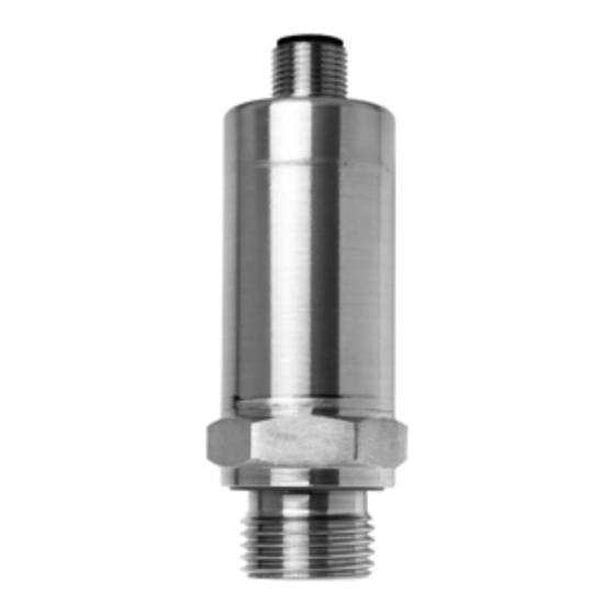
Page 7: Dimensions, Tightening Torques, Wrench Size
1 Introduction Dimensions, tightening torques, wrench size Ceramic version With process connection G 1/4" With process connection NPT 1/4" according to EN 837 according to EN 837 M12 x 1 M12 x 1 Ø 26,8 Ø 26,8 Ø 5 NPT ¼"-18 Ø... -
Page 8: Identifying The Device Version
The device type no. can help to localize the associated device description file (EDS) as part of the file name. Load EDS: 1. Go to web page https://country.burkert.com/ 2. Select your country 3. Click on Continue to website 4. Confirm or change cookie settings 5. - Page 9 2 Identifying the device version figure and verify the device. This can be used to configure and check the device. Date of The device's date of manufacture (year and calendar week) is part of the fabri- manufacture cation number. Digits 12 to 15 denote the year of manufacture and the calen- dar week.
-
Page 10: Transmitter
3 Transmitter Application Transmitters are used for acquiring pressures or temperatures in liquid or gas- eous media. The measurements from the pressure or temperature sensors are digitized and made available for further processing via the CANopen. Several useful extra functions are implemented through the DS 404 device profile. All settings can be made using standard CANopen software tools. -
Page 11: Operation
3 Transmitter 3.2.1 Operation The analog signal from the pressure cell or the temperature sensor is dig- itized. The pressure or temperature signal is digitally calibrated at the factory. The temperature signal is linearized. Undesirable signal fluctuations can be suppressed through the (adjust- able) filter constant. -
Page 12: Setup Program
CANopen object dictionary (EDS file) and can be set using standard CANopen software tools. An appropriate EDS file is available for all device types. The file is downloadable free of charge from the Bürkert home page www.burkert.com using the product typ number 8312 in the search field. -
Page 13: Installation
4 Installation Electrical connection Earth the instrument at the pressure connection. The bus ends must be provided with a line termination. Chapter 4 “Installation” / “Line termination”, page 14. Bus cable - the bus specifications to ISO 11 898 must be observed - cable diameter 6 to 12 mm - conductor cross-section up to 1.5mm per core... - Page 14 4 Installation Line termination The CAN bus has a linear topology. Each end of the bus must be terminated with a 120 resistor, to avoid signal reflections and, as a consequence, trans- mission problems. Node 1 Node n Knoten 1 Knoten n CAN-H CAN bus...
-
Page 15: Commissioning
5 Commissioning Setting the CAN baud rate General The baud rate is set to 500 kbaud ex-factory. The CAN baud rate can be set both via SDO telegrams (object dictionary) and LSS. Setting via SDO The CAN baud rate can be reprogrammed via the CANopen object dictionary, index 0x2001. -
Page 16: Setting The Node Id
5 Commissioning Setting the node ID General Ex-factory, the node ID is preset as follows: for 8312: The node ID can be set both via SDO telegrams (object dictionary) and LSS. Each node ID may only be allocated once on the bus. Setting via SDO The node ID can be reprogrammed via the CANopen object dictionary, index 0x2000, thereby enabling all transmitters of a plant, for instance, to be pro-... -
Page 17: Canopen Function
6 CANopen function Overview of communication functions Communica- The CAN interface communication functions correspond to the CANopen tion profile communication profile DS-301. Objects Data exchange with CANopen devices takes place in the form of objects. The table below contains the supported objects; these will be explained in the sections that follow. -
Page 18: Nmt
6 CANopen function The transmitters support both the CANopen minimum bootup and the auto- operational bootup. NMT user data Network management Network management of object data command Byte 1 Byte 2 Command specifier Node ID Node start (6) 0x01 0 —127 (0 = all devices) Node stop (7) 0x02... -
Page 19: Sync
6 CANopen function Sync The PDOs of the transmitter can be configured as “synchronous”. When a Sync object has been received, the corresponding PDO will be transmitted. Settings for The PDO transmission type can be switched between synchronous (controlled Sync by the master) and asynchronous (event-controlled) in the object dictionary (0x1800,2 or 0x1804,2). -
Page 20: Pdo
6 CANopen function Setting for Factory setting: once per second (= 1000 msec) Emergency EMCY time Setting the object 0x2002 milliseconds 0 — 65535 (0 = not repeated) 1 or 2 transmit PDO(s) (process data object) are available for the measure- ments. - Page 21 6 CANopen function PDO output The graphic below shows possible events that will lead to a PDO telegram control being transmitted. The setting options are described below. For calculating the measurement and status, see chapter 7 “Device function”, page 26. only possible in asynchronous mode...
-
Page 22: Sdo
6 CANopen function Operational: When changing to the “Operational” status, a PDO is sent once. Sync: If the transmission type has been configured as “synchronous”, a PDO is sent on receipt of the Sync object. Description see chapter 6.3 “Sync”, page 19. RTR (Remote Transmission Request): If requested by a PDO recipient, a PDO is sent. -
Page 23: Heartbeat
6 CANopen function Heartbeat The Heartbeat object signals the presence of a transmitter, thereby ensuring system reliability. It provides a simple alternative to the Node Guarding proto- col (see chapter 6.8 “Node Guarding”, page 24). Heartbeat The heartbeat message (heartbeat event) consists of one byte. In this byte, the user data NMT status of the internal status machine is coded as follows: Bootup:... -
Page 24: Node Guarding
6 CANopen function Node Guarding The Node Guarding object provides an alternative to the Heartbeat object (see chapter 6.7 “Heartbeat”, page 23). It indicates the presence of a transmitter, thereby ensuring system reliability. Unlike Heartbeat, in the case of Node Guarding the NMT master (usually a PLC) sends a request, which is answered by the NMT slave (here: the CANtrans transmitter). -
Page 25: Lss
6 CANopen function Settings for The settings for the Node Guarding slave are made in the object directory, via Node Guarding the parameters Guard Time (0x100C) and Live Time Factor (0x100D). The Node Guarding slave calculates its own live time to be the product of these two parameters. -
Page 26: Device Function
7 Device function Device profile The transmitters operate according to the CANopen device profile DS-404 “Measuring Devices and Closed-Loop Controllers”. The graphics below show the signal flow of the measurement through the transmitter functi- ons. Some functions can be set by the user. The setting options are described in Chapter 8 “Object dictionary”, page 28. -
Page 27: Data Flow: Temperature Channel
7 Device function Data flow: temperature channel Filter constant Emergency 0x61A1 output Linearization Sensor monitoring: Status A/D conversion Temperature Filter Pt1000 0x6150,Bit0 sensor fault with calibration sensor -200 to 850°C Field value 0x6100 temp. in ohms Offset Offset Factor Decimal places 0x6127 0x6124 0x6126... -
Page 28: Object Dictionary
1 or 2 subindices. Accordingly, the 8312, for example, only has the sub- index 1 = pressure channel. For all device types, the corresponding EDS file is downloadable free of charge from the Bürkert home page www.burkert.com. Index Sub-... - Page 29 8 Object dictionary 0x1800 PDO 1 Controls the transmis- Communica- sion conditions for 1st tion Parameter 0x01 UINT32 RW COB-ID ID with which the PDO 0x180 — 0x57F is transmitted bit 0x800000000 set = PDO inactive ex-factory: 0x180+Node-ID 0x02 UINT8 Transmission Transmission mode 0x01 = synchronous...
- Page 30 8 Object dictionary 0x2002 - UINT16 RW EMCY_Time Time for cyclic trans- 0 — 65535 msec mission of error 0 = once messages ex-fact. 1000 msec 0x3100 0x01 float Al PV Min 1 Drag pointer minimum value 0x02 float Al PV Min 2 as subindex 0x01, for devices with 2 sensors 0x3101 0x01...
- Page 31 8 Object dictionary 0x6127 0x01 float Al Scaling Scaling offset ex-factory: 0 Offset 1 e.g. 0.0, to show pressure not as 0x02 float Al Scaling as subindex 0x01, for 0 — 100% but as Offset 2 devices with 2 sensors 0 —10 bar;...
- Page 32 8 Object dictionary 0x6150 0x01 UINT8 Al State 1 Error status (as also in PDO) bit 0 = sensor faulty bit 1 = overrange (value > object 0x6149) bit 2 = underrange (value < object 0x6148) 0x02 UINT8 Al State 2 as subindex 0x01, for devices with 2 sensors 0x61A1 0x01...
-
Page 33: Programming Examples
9 Programming examples General You can compile simple CAN messages yourself and transmit them to the individual CAN devices by using the free PCANView program (supplied by Peak, www.peak-system.com). Function To start with, you will be asked to select the baud rate. It can be set by choosing one of the values displayed in the program window. - Page 34 9 Programming examples (2) (3) (4) For an overview of the communication functions see Chapter 6.1 “Overview of communication functions”, page 17. The ID (Hex) (1) determines the telegram type (PDO, SDO or LSS), the address and the priority of the message. The lowest ID has the highest priority in the case of CAN telegrams.
-
Page 35: Heartbeat Producer Time
9 Programming examples Heartbeat Producer Time (see Chapter 6.7 “Heartbeat”, page 23) Alteration of the time for the cyclic transmission of a sign of life at 5000msec intervals (1388hex) Node ID: COP ID: Object index: 1017 Subindex: Value: 1388 Boot mode “Minimum bootup” (see Chapter 6.2 “NMT”, page 18) After switch-on, the transmitter should adopt the preoperational state. -
Page 36: Setting The Node Id
9 Programming examples Setting the node ID (see Chapter 5.2 “Setting the node ID”, page 16) Set node address to the value 120 (78hex) via SDO A change of the node ID only becomes effective after a reset ! Node ID: COP ID: Object index: 2000 Subindex:... -
Page 37: Reading Out The Maximum Value
9 Programming examples 9.10 Reading out the maximum value (see Chapter 7.2 “Data flow: pressure channel”, page 26) Readout of the largest value that was registered. Node ID: COP ID: Object index: 3101 Subindex: Value: Read procedure 9.11 Reading out the measurement in “Float” format (see Chapter 7.2 “Data flow: pressure channel”, page 26) Read measurement as “Float”... - Page 38 Bürkert SAS Rue du Giessen F-67220 TRIEMBACH-AU-VAL...
Need help?
Do you have a question about the 8312 Series and is the answer not in the manual?
Questions and answers