Table of Contents
Advertisement
Quick Links
Download this manual
See also:
User Manual
Advertisement
Table of Contents

Related Manuals for RGBlink M1


Summary of Contents for RGBlink M1
- Page 1 M1 Quick Start Support signal cross conversion Support pixel-to-pixel scaling Support four modular inputs Support HDMI & SDI outputs Support touch screen control Integrated audio Support configurable PIP Support Transition effects, DSK, Blending ...
-
Page 2: Table Of Contents
CONTENTS Product Introduction.............................. 3 Packing Configuration..............................4 Hardware Orientation..............................5 Front Panel................................5 Rear Panel................................9 Using Your Product..............................10 Menu Structure..............................10 PST Mode................................12 PGM Mode................................17 Switching Mode..............................18 Set the Output Parameter..........................19 Using Black Out..............................21 Lock Front Panel............................... 22 Language/语言..............................22 System Setting..............................22 Factory Reset..............................23... -
Page 3: Product Introduction
Fade or Wipe. M1 is not only a traditional video mixer, but also a video scaler by its integration pixel scale engine for the modern displays, including LED display, which user doesn’t need to have a video scaler behind. -
Page 4: Packing Configuration
Packing Configuration AC Power Cable USB Cable HDMI to DVI Network Cable Cable Screw Driver Cable DVI a HDMI Note: AC Power Cable supplied as standard according to destination market. USB is contained on the Warranty/Registration Card. Please keep. 4/25... -
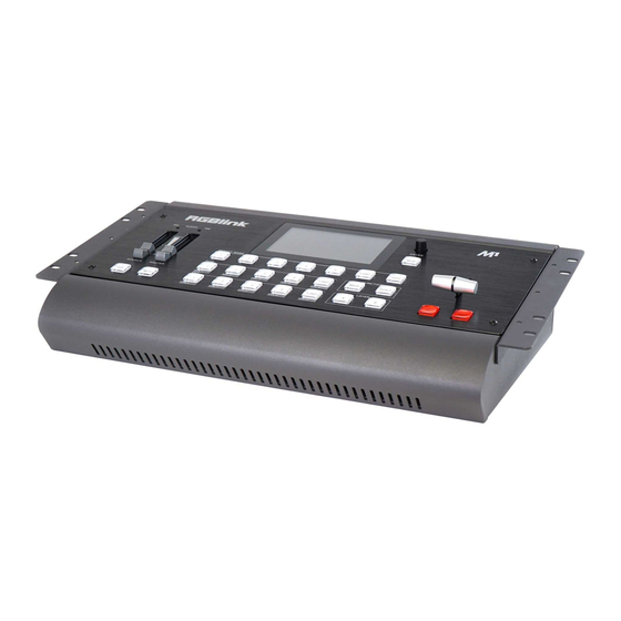
Page 5: Hardware Orientation
Hardware Orientation Front Panel Panel Instruction Audio adjust area Menu and LCD display area Audio input area Switching mode area PGM output area and Logo button Function area PST output area and Logo button Layer selection area 5/25... -
Page 6: Audio Adjust Area
MUTE MUTE is for single audio output/Mix audio output Audio input area SAVE To adjust M1 audio input and output. LOAD Press load button once to lock audio; press load button for 3 seconds to factory reset. 1/2/3/4/5 The button 1/2/3/4/5 is to select audio input. -
Page 7: Pst Output Area And Logo Button
PST output area and Logo button LED INDICATOR The button 1/2/3/4/LOGO is lit when the signal or background input is selected for use. PST AREA For indicating, user can not change the channel or set the size or position in this area. LOGO For switching from PGM to test pattern. -
Page 8: Layer Selection Area
Funtion Area MASK Choose the button to full screen the selected layer SCALE Press this button to set PIP in PST window. Remar: Press the button to open PIP, select A/B layer to close PIP. Layer Selection Area For adding or deleting the layer, the button light is lit when add the layer, off when delete the layer, and flash when select the layer. -
Page 9: Rear Panel
Rear Panel Input Interface Optional Input Module 4 input card slots, supports input signals including DVI, HDMI, USB, SDI. Each DVI module supports 1 DVI-I input and compatible CVBS, VGA,YPbPr. Each HDMI module supports 1 HDMI-A input Each USB module supports 1 USB-B input and 1 USB backup. Each SDI module supports 1 SDI input and 1 SDI loop out. -
Page 10: Using Your Product
Using Your Product Menu Structure The menu structure is shown on the LCD Screen and in the figure below: LCD Touch Screen Menu Instruction Return Button Homepage BLEND Information Page FREEZE Input Resolution Display BLACK Output Resolution Display Audio In Input Menu Audio Out Output Menu... - Page 11 Customized version for broadcasting 11/25...
-
Page 12: Pst Mode
PST Mode M1 supports 1 HDMI preview output, and it supports the functions as below: Signal Selection Push any button in PGM or PST output area, for example, push the button [5], the border of signal 5 will change to yellow, and the signal in PGM monitor will be changed to signal 5. - Page 13 Scale and Crop the Layer 1. Push any button of [A] to [B] in Layer Selection Area, the light is flashing when the layer is selected. 2. Touch on LCD screen, and enter to the menus as follows: Use the rotary knob to adjust the size of the layer. ->...
- Page 14 Transitions Setting 1. Touch the transition buttons in LCD screen, M1 supports 15kinds of wipe modes: Touch the transition button , user can select ←[]→. Touch the transition button , can select L→R. Touch the transition button , user can select T→B.
- Page 15 2. Select the Audio input 1-4 for setting : Audio Source Sel Embedded Audio Gain Audio Delay 0 ms Audio Source Sel: Embedded or External Audio Gain: The adjustment range is between 0~100 Audio Delay: The adjustment range is between 0~20ms Audio Out Setting 1.
- Page 16 Mask Setting 1. Push [MENU] button, and enter to the menu items. Turn the rotary knob, select <Mask>option on LCD screen, rotary the knob or touch the directly to confirm. Mask Mask Mask Layer Mask & PIC POS 2. Select the Mask for setting : Mask Heart Oval...
-
Page 17: Pgm Mode
PGM Mode 1. Switch the edited PST image to program by pushing the [CUT], [TAKE] button or T-bar, and then the PGM image will return to PST state, which can be edited. 2. There are 1 HDMI output and 1SDI output for program, and maximum realize 1920x1080 output. 17/25... -
Page 18: Switching Mode
Switching Mode 1. T-BAR switch: Switch the PST image to program with wipe and fade by T-bar. 2. CUT switch: Seamless switch the PST image to program by pushing [CUT] button. 3. TAKE switch: Switch the PST image to program with wipe and fade by pushing [TAKE] button. 4. -
Page 19: Set The Output Parameter
Set the Output Parameter 1. Select the Output Resolution Push the [MENU] button, and enter to the menu items, turn the rotary knob and select <Output> or Push the rotary knob to confirm, and enter to the menus as below: Output Format Output Setting External Sync... - Page 20 3. External Sync External Sync External Input No Input Format 1920x1080 @60 External Including option Off and On, Input will shown as actual input resolution. Format support choose 2 default resolution: 1280x720 @60 & 1920x1080 @60. 4. Test Pattern Test Pattern Output Test Pattern Green...
-
Page 21: Using Black Out
Using Black Out Black out description: Black signal realizes one-key-touch to a black screen. M1 provides black effect processing for program output and preview output, with cut black effect. Operation is as below: Touch the [BLACK] button or key, then the program output is cut to black. -
Page 22: Lock Front Panel
Lock Front Panel 1. Push the [MENU] button, and enter to the menu items, turn the rotary knob and select enter to the Lock Front Panel, if select “on”, then LCD screen shown follows: Locked Panel! Press Menu key For 3 seconds to Unlock! 2. -
Page 23: Factory Reset
Fader Correction: Shown Fader Correction steps. Key Board Test: LED Light Test select “On”, LED light for each key on front panel will be lit one by one, and KEY Value shown “MENU”. LED Light Test select “Off”, LED light for all keys will be off, and KEY Value shown “MENU”. Factory Reset 1. -
Page 24: Contact Information
All video products are designed and tested to the highest quality standard and backed by full 3 years parts and labor warranty. Warranties are effective upon delivery date to customer and are non-transferable. RGBlink warranties are only valid to the original purchase/owner. Warranty related repairs include parts and labor, but do not include faults resulting from user negligence, special modification, lighting strikes, abuse(drop/crush), and/or other unusual damages.
Need help?
Do you have a question about the M1 and is the answer not in the manual?
Questions and answers