Table of Contents
Advertisement
Quick Links
Advertisement
Table of Contents

Related Manuals for Badger Meter Data Industrial 3100 Series


Summary of Contents for Badger Meter Data Industrial 3100 Series
- Page 1 Industrial Flow Monitor Series 3100 User Manual CTL-UM-01026-EN-05 (October 2017)
- Page 2 Industrial Flow Monitor, Series 3100 Page ii CTL-UM-01026-EN-05 October 2017...
-
Page 3: Table Of Contents
User Manual CONTENTS Introduction . . . . . . . . . . . . . . . . . . . . . . . . . . . . . . . . . . . . . . . . . . . . . . . . . . . . . . . . . . . . . . . . . . . . . . . . . . 5 Advanced Standard Features . - Page 4 Industrial Flow Monitor, Series 3100 RS485 Communication Flowchart . . . . . . . . . . . . . . . . . . . . . . . . . . . . . . . . . . . . . . . . . . . . . . . . . . . . . . . . 22 Solid-State Switch and Form C Outputs .
-
Page 5: Introduction
Introduction INTRODUCTION The Badger Meter® Data Industrial® Series 3100 flow monitor is an economical, dual channel, full featured, digital rate and totalizing monitor, compete with setpoint control, scaled pulse output, analog outputs, analog PID controller, USB, and RS485 Modbus and BACnet communication . -
Page 6: Unpacking & Inspection
Unpacking & Inspection UNPACKING & INSPECTION Upon opening the shipping container, visually inspect the product and applicable accessories for any physical damage such as scratches, loose or broken parts, or any other sign of damage that may have occurred during shipment . OTEE: If damage is found, request an inspection by the carrier’s agent within 48 hours of delivery and file a claim with the carrier . -
Page 7: Wall Mount Installation
Installation Wall Mount Installation Badger Meter does not currently offer a wall mount enclosure for this product . However, Series 3100 flow monitors can be wall mounted in the field into any appropriate customer-supplied enclosure . Electrical Power MPORTANT Before applying power to this unit, check the Model # label: The Series 3100 flow monitor can be ordered as low voltage 12…24V AC/ DC (3100-0x) or as high voltage 120/240V AC (3100-1x). -
Page 8: Input Sensor Wiring
Installation Input Sensor Wiring The Series 3100 flow monitor is a Dual Channel unit . Either a single input, or any combination of two pulse or analog inputs can be used . The pulse inputs are extremely versatile, designed to accept either two-wire (Data Industrial 200 Series), three- wire pulse inputs (4000 Series) or zero-crossing sine wave inputs (turbines with a magnetic coil pickup) . -
Page 9: Analog Input
Analog Input As an alternative to the pulse inputs, the Badger Meter Series 3100 also accepts up to two analog inputs . The input is non-isolated, but can accept 0…1V DC, 0…5V DC, 0…10V DC, 0…20 mA and 4…20 mA with both factory-defined and custom units of measure . - Page 10 Installation Sensor Input Card Red Label 14 Pin Connector Relay 1 NO Relay 1 NC Relay 1 COM Indicator Light Relay 2 NO Normally Open or other Relay 2 NC Master Valve Signaling Device Relay 2 COM Relay 3 NO Relay 3 NC Relay 3 COM Relay 4 NO...
-
Page 11: Normally Open Solid-State Switch
Installation Normally Open Solid-State Switch Sensor Input Card Red Label 14 Pin Connector Relay 1 NO Relay 1 NC Relay 1 COM Relay 2 NO Relay 2 NC Mechanical Relay 2 COM Counter Relay 3 NO Relay 3 NC Relay 3 COM Relay 4 NO Power Supply Relay 4 NC... -
Page 12: Rs485 Communication Wiring
Installation RS485 Communication Wiring Analog Output Card Yellow Label 9 Pin Connector RS485 B (+) RS485 (+) RS385 A (-) RS485 (-) Shield RS485 Iso. GND (REF) CH2 Loop (+) CH2 Loop (-) Series 3700 or other CH2 GND Modbus or BACnet Master Device CH1 Loop (+) CH1 Loop (-) -
Page 13: Keypad/Display Menu Navigation
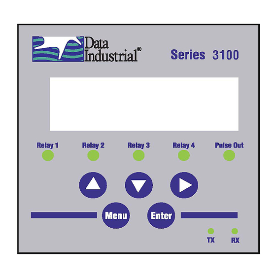
. Two of the keys (Menu and Enter) serve a single function while the three remaining keys () serve dual purposes . When the flow monitor is first powered up, it performs internal testing while displaying “Badger Meter DIC Initializing . ” At the end of the internal testing cycle, the main display appears . -
Page 14: Programming
Programming PROGRAMMING Selection Screens Press MENU while the normal display is shown to access the programming mode . In this mode, press one of the three arrow keys () to select the option displayed above that key . On option list screens, use the arrows to scroll through a list of choices, like a pull-down menu . - Page 15 User Manual INTENTIONAL BLANK PAGE October 2017 CTL-UM-01026-EN-05 Page 15...
-
Page 16: Programming Flowchart
Programming Programming Flowchart RESET SETUP DIAG Continued at A RESET Enter password on next page. FLOW1 FLOW2 0000 Appears only if Setup Password is enabled. Reset ow x? OK CANCEL Enter password 0000 SETUP Reset ow x? PWORD DSPY FLOW1 RESET Continued at B on next page. - Page 17 Programming Programming Flowchart (continued) Continued from A RESET SETUP DIAG on previous page. DIAG DIAG ERROR MODL# SER# REV# Model # Serial # Firmware rev: 3100XX XXXXXX v1.2.29 Error codes: 000 000 000 000 SETUP SETUP SETUP SETUP PWORD DSPY FLOW1 FLOW2 RLY1 RLY2 RLY3 RLY4 Pulse AOUT1 AOUT2 COMM...
-
Page 18: Flow Inputs Flowchart
Programming Flow Inputs Flowchart Flow 1 setup RATE TOTAL SENSR Continued Flow X rate Flow X total Flow X total UNITS #.DIG CUST UNITS #.DIG CUST RESET at A on next page. Reset BTU total Custom units PASSWD RESET LABEL CONV Enable password? Reset total NOW? 1 UNIT =... - Page 19 Programming Flow Inputs Flowchart (continued) Continued from previous page. Sensor 1 type Flow 1 sensor TYPE xxxx xxxx Flow 1 sensor Pulse DI TYPE AVG DICAL DI Sensor Cal. KNUM OFFSET Flow 1 timeconst DI sensor K num Pulse K-Factor Flow 1 sensor -0.00000000 sec -0.00000000...
-
Page 20: Relays And Pulse Outputs Flowchart
Programming Relays and Pulse Outputs Flowchart SETUP FLOW2 RLY1 RLY2 RLY3 RLY4 Pulse Relay 1 (or Pulse) FUNC xxxxx xxxxx Relay 1 (or Pulse) Manual Control FUNC MANUAL Relay 1 (or Pulse) Relay 1 (or Pulse) Relay 1 (or Pulse) Totalizer ON [OFF] FUNC INPUT UNITS... -
Page 21: Analog Outputs Flowchart
Programming Analog Outputs Flowchart SETUP AOUT1 COMM Analog output 1 FUNC RANGE SCR Analog function Analog output 1 Analog output 1 Analog output 1 Flow Rate FUNC RANGE SCR UNITS LOW HIGH Analog 1 units Analog output Adjust 20 mA Drive source 0 mA = ? 20 mA = ? -
Page 22: Rs485 Communication Flowchart
Programming RS485 Communication Flowchart Comm NET BAUD ADDR Network Comm Disable Comm MODBUS BAUD ADDR Network Baud Rate MODBUS Address MODBUS 1200 2400 9600 19200 38400 76800 Comm BACnet/MSTP BAUD ADDR DEVID Network Baud Rate MSTP Address MSTP Max master Device Instance BACnet/MSTP Auto... -
Page 23: Solid-State Switch And Form C Outputs
Programming Solid-State Switch and Form C Outputs The four Form C mechanical relays, and one NO solid-state switch pulse output are completely independent, electrically isolated and can be programmed as either pulse or setpoint outputs . Totalizer Pulse Output When the Totalizer function is selected, the unit of measure and resolution are independent of the displayed units, and can be programmed where 1 pulse occurs once every 0000000 .1…... -
Page 24: Communication
Programming Communication RS485 COM Port Configuration The RS485 is very simple to configure . 1 . Select the communications type: Modbus or BACnet . 1 . Choose the BAUD Rate: Auto, 300, 1200, 2400, 9600, 19200, 38400, or 76800 to match the rest of the devices on the network . -
Page 25: Bacnet
Press the “Enter Key”. Both the Rx and Tx LED’s on the front of the Series 3000 sh flash once, and October 2017 CTL-UM-01026-EN-05 Page 25 the “Badger Meter DIC … Software Version…” text message should appear. The Series 3000 is now communicating ready to take commands from the list below... -
Page 26: Usb Command List
Figure 3: COM4 properties screen 4 . Press ENTER . Both the Rx and Tx LEDs on the front of the Series 3100 flash once and the “Badger Meter DIC…Software he “Enter Key”. Both the Rx and Tx LED’s on the front of the Series 3000 should Version…”... - Page 27 Programming Input Channel Configuration flow [1-2] sensor type = [0-4] -- flow sensor type: 0: PulseDI, 1: PulseKFactor 2: PullupKFactor* 3: SineKFactor* 4: Analog* flow [1-2] sensor dical k = [x] -- DI-type flow sensor k flow [1-2] sensor dical off = [x] -- DI-type flow sensor offset flow [1-2] sensor kfact = [x] -- K factor for non-DI sensors flow [1-2] sensor analog units = [0-19] -- flow units for analog input flow [1-2] sensor analog range = [0-4] -- current range for analog input...
- Page 28 Programming Relay Output Configuration relay [1-5] func = [0-9] -- relay function; relay 5 is the pulse output 0: Totalizer 1: Alarm 2: Manual Control relay [1-5] input = [0-8] -- relay input; depends on source for totalizer: 0: Flow 1 Total 1: Flow 2 Rate 2: Flow Sum Rate 3: Flow 1-2 Rate...
-
Page 29: Troubleshooting
Troubleshooting TROUBLESHOOTING Trouble Codes Relay 1 totalizer rate exceeded Relay 2 rate exceeded Relay 3 rate exceeded Relay 4 rate exceeded Pulse out rate exceeded Error reading EEPROM on faceplate Error writing EEPROM Analog Input card missing Temperature Input card missing Invalid flow units configured Invalid volume units configured Bad input frequency... -
Page 30: Specifications
Specifications SPECIFICATIONS DC current draw (~ 280 mA) Voltage 12…24V DC/AC (limit: 8…35V DC); (limit: 8…28V AC) AC Power rating (~5 VA) Display 16 character by two line alphanumeric Dot Matrix 3/8 in . (7 .95 mm) high backlit LCD Operating Temperature –4…158°... -
Page 31: Ordering Matrix
Ordering Matrix ORDERING MATRIX Series 3100 Flow Monitor Ordering Matrix Example: 3100 – Series Flow Monitor 3100 – Power Low Voltage Supply 12…24V AC/VDC High Voltage 120/240V AC Mounting Panel Mount Figure 4: Ordering matrix October 2017 CTL-UM-01026-EN-05 Page 31... - Page 32 The Americas | Badger Meter | 4545 West Brown Deer Rd | PO Box 245036 | Milwaukee, WI 53224-9536 | 800-876-3837 | 414-355-0400 México | Badger Meter de las Americas, S.A. de C.V. | Pedro Luis Ogazón N°32 | Esq. Angelina N°24 | Colonia Guadalupe Inn | CP 01050 | México, DF | México | +52-55-5662-0882 Europe, Eastern Europe Branch Office (for Poland, Latvia, Lithuania, Estonia, Ukraine, Belarus) | Badger Meter Europe | ul.
Need help?
Do you have a question about the Data Industrial 3100 Series and is the answer not in the manual?
Questions and answers