Table of Contents
Advertisement
Operation
Manual
INVERTER-DRIVEN
MULTI-SPLIT SYSTEM
HEAT PUMP
AIR CONDITIONERS
Type
(H,Y,C)IC4008B21S
(H,Y,C)IC4012B21S
(H,Y,C)IC4015B21S
(H,Y,C)IC4018B21S
4-Way Cassette
(H,Y,C)IC4024B21S
(H,Y,C)IC4030B21S
(H,Y,C)IC4036B21S
(H,Y,C)IC4048B21S
IMPORTANT:
READ AND UNDERSTAND
THIS MANUAL BEFORE
USING THIS HEAT PUMP
AIR CONDITIONER.
KEEP THIS MANUAL FOR
FUTURE REFERENCE.
Model
P5417055
Advertisement
Table of Contents

Related Manuals for Johnson Controls HIC4008B21S


Summary of Contents for Johnson Controls HIC4008B21S
- Page 1 Operation Manual INVERTER-DRIVEN MULTI-SPLIT SYSTEM HEAT PUMP AIR CONDITIONERS Type Model (H,Y,C)IC4008B21S (H,Y,C)IC4012B21S (H,Y,C)IC4015B21S (H,Y,C)IC4018B21S 4-Way Cassette (H,Y,C)IC4024B21S (H,Y,C)IC4030B21S (H,Y,C)IC4036B21S (H,Y,C)IC4048B21S IMPORTANT: READ AND UNDERSTAND THIS MANUAL BEFORE USING THIS HEAT PUMP AIR CONDITIONER. KEEP THIS MANUAL FOR FUTURE REFERENCE. P5417055...
- Page 3 Important Notice ● Johnson Controls Inc. pursues a policy of continuing improvement in design and performance in its products. As such, Johnson Controls Inc. reserves the right to make changes at any time without prior notice. ● Johnson Controls Inc. cannot anticipate every possible circumstance that might involve a potential hazard.
-
Page 4: Table Of Contents
TABLE OF CONTENTS 1. Introduction ..............................1 2. Safety Instructions ............................1 3. Before Operation .............................5 3.1 Operating Range ............................5 3.2 Efficient Use of Indoor Unit ........................5 3.3 Efficient Use of Cooling and Heating ......................6 4. Name of Parts and Indication of Safety Consideration ...................7 4.1 Indoor Unit ..............................7 4.2 Wired Controller (CIW01) ........................8 5. -
Page 5: Introduction
● This system should be installed by personnel certified by Johnson Controls, Inc. Personnel must be qualified according to local, state and national building and safety codes and regulations. Incorrect installation could cause leaks, electric shock, fire or explosion. In areas where Seismic ‘’Performance requirements are specified, the appropriate measures should be taken during installation to guard against possible damage or injury that might occur in an earthquake. - Page 6 This unit is the pressurized system. Never loosen threaded joints while the system is under pressure and never open pressurized system parts. ● Johnson Controls will not assume any liability for injuries or damage caused by not following steps outlined or described in this manual. Unauthorized modifications to Johnson Controls products are prohibited as they…...
- Page 7 Operation ● Do not insert fingers or objects into air inlet/outlet. Injury can result from rotating fan blades or energized electrical components. ● Do not touch the wired controller with wet hands. Failure of the wired controller or an electrical shock can result.
- Page 8 Repair / Relocation ● When the air conditioner is to be repaired or transported to a new location, contact your distributor or contractor. If the repair and the installation are not completed, electric shock or fire can result. Others ● Turn OFF all power at the main power source before performing maintenance work. Failure to do so can result in damage to internal components with severe or fatal electrical shock.
-
Page 9: Before Operation
Before Operation NOTICE Apply power to the outdoor unit(s) at least 12 hours prior to system operation to allow for preheating of the compressor oil. Do not start the system immediately without preheating the compressor. Otherwise, the compressor can be damaged. Check that the outdoor unit is free of ice and snow cover. -
Page 10: Efficient Use Of Cooling And Heating
Efficient Use of Cooling and Heating COOLING HEATING (1) Airflow Direction (1) Airflow Direction The appropriate air outlet angle is approximately 35 The appropriate air outlet angle is approximately 60 If cooling is not sufficient, change the airfow direction. If heating is not sufficient, change the airflow direction. Each louver angle can be changed approximately 5 Each louver angle can be changed approximately 5 per step by the wired controller. -
Page 11: Name Of Parts And Indication Of Safety Consideration
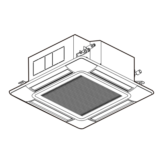
Name of Parts and Indication of Safety Consideration Safety labels are affixed to the indoor unit in order to ensure safe use. Read and understand this manual before using the indoor unit. Indoor Unit WARNING Label Motion Sensor (Only for Decorative Panel with Motion Sensor) Indoor Unit... -
Page 12: Wired Controller (Ciw01)
Wired Controller (CIW01) Following is an example of how the CIW01 is utilized. If other models of the controller are utilized, operate the unit according to the manual for that controller. The example below references the control panel and all adjustable settings. -
Page 13: Operation Method
Operation Method Basic Operation By pressing “ ”or “ ”, the icon “ ” will move between “MODE”, “SPEED”, Menu “LOUV.” and “TEMP”. Item Selection Back/Help With “MODE”, “SPEED”, “LOUV.” or “TEMP” selected, press “ ” or “ ”. Menu The setting is changed. -
Page 14: Cooling / Heating / Fan Operation
Cooling / Heating / Fan Operation Heating Operation is for VRF systems only and is not available for typical systems. Function * Cooling Operation: To decrease room temperature. * Heating Operation: To increase room temperature. * Dry Operation: To decrease humidity in the room. * Fan Operation: To increase air circulation in the room. -
Page 15: Temperature Setting
Temperature Setting Press “ ” or “ ” and select “TEMP”. Menu Back/Help By pressing “ ”, temperature is increased by 1 F (0.5 Menu (Max. 86 F (30 By pressing “ ”, temperature is Back/Help decreased by 1 F (0.5 COOL, FAN operation: Min. -
Page 16: Fan Speed
Fan Speed Press “ ” or “ ” and select “SPEED”. Menu Back/Help By pressing “ ” or “ ”, fan speed is changed as follows. Menu Back/Help HIGH 2 HIGH AUTO ● During the dry operation, the fan speed is automatically adjusted to “LOW” and cannot be changed to any other fan speed. -
Page 17: Louver Swing Direction
Louver Swing Direction Press “ On/Off”. Make sure that the operation is started. Menu Press “ ” or “ ” and select “LOUV.”. Back/Help By pressing “ ” or “ ”, the louver direction are changed as follows. Menu Back/Help Step LCD Indication Approx. -
Page 18: Individual Louver Setting
Individual Louver Setting Function ● This setting is available only for indoor models equipped with the individual louver. ● Each louver angle can be set individually. Example Units equipped with Auto-Swing have a set of options to allow for airflow adjustment from vertical to horizontal. - Page 19 Press “ ” or “ ” and select the louver direction from 1 to 4 (as shown). The selected louver is opened and the other louvers Individual Louver Setting:01-02 are seen horizontally. Adjust air direction & louver angle. Sel. Adj. Entr Back Rtrn...
-
Page 20: Cancellation Of Louver Setting
5.7.2 Cancellation of Louver Setting Press “Menu”. Menu Select “Individual Louver Setting” from the menu by pressing “ ” or “ ” and Menu 15:10(Fri) Back/Help press “OK”. Individual Louver Setting Louver Open/Close The individual louver setting menu is VENTI displayed. -
Page 21: Motion Sensor
Motion Sensor 5.8.1 Function The decorative panel (P-AP160NAE1) is equipped with four motion sensors and one radiation sensor. ● Motion Sensor Detecting Area These sensors can detect human activity by measuring the level of change in infrared light Area of Motion Sensors emitted by humans or objects. -
Page 22: Descriptions For Setting Items
Function 2 Adjusting Capacity by Increase or Decrease in the Number of People (1) In instances where people are gathered within or are beyond the range of the motion sensor. The air conditioning capacity is adjusted by the automatic setting temperature correction depending on human activity and movements of a heat source in the detecting area of the motion sensor . -
Page 23: Setting The Motion Sensor
5.8.3 Setting the Motion Sensor Press “Menu”. Menu Select “Motion Sensor Setting” from the menu by pressing “ ” or “ ” and press Menu 15:10(Fri) Back/Help Individual Louver Setting “OK”. Louver Open/Close VENTI Total Heat Exchanger SET Menu Motion Sensor Setting Sel. - Page 24 Press “ ” or “ ” and select “Check Motion Sensor Setting interval”. Sensor Menu If absent Running Check interval 30MIN Back/Help Sel. Adj. Entr Rtrn Back The display will display: “30MIN”, “60MIN”, “90MIN”, “120MIN”, and “180MIN” in Motion Sensor Setting Sensor Menu order by pressing “...
-
Page 25: Comfort Setting
Comfort Setting 5.9.1 Setting of “Control Cool Air” (Cold Draft Control during Cooling Operation) (1) Function This function controls the overcooling airflow to prevent of cold draft. (2) Setting Items * OFF : This function is not available. * LOW : The over-cooling airflow temperature is controlled low degree. * MID : The over-cooling airflow temperature is controlled medium degree. - Page 26 (3) Supplement of Function • The louver angle is adjusted by the motion sensor to compensate for the presence or absence of human activity and can be set for manual override at the wired controller. • Each of the four louvers can move independently of the others. •...
-
Page 27: Setting Of "Floor Heat Control" (Radiation Sensor During Heating Operation)
5.9.3 Setting of “Floor HEAT Control” (Radiation Sensor during Heating Operation) (1) Function If a steep temperature difference is detected between the radiation temperature and the setting temperature, this function heats the entire room efficiently by adjusting airflow direction and airflow volume. -
Page 28: Creating Comfort Settings
5.9.5 Creating Comfort Settings Press “Menu”. Menu Select "Comfort Setting” from the menu by pressing “ ” or “ ” and press “OK”. Back/Help Menu Back/Help "Motion Sensor Setting” is displayed. The highlighted item is changed to “Control Cool Air”, “Louver in COOL”, “Louver in HEAT”... -
Page 29: Automatic Heating/Cooling Operation
An automatic heating/cooling operation and setback operation requires extra settings. Contact your distributor or contractor for details. 5.10 Automatic Heating/Cooling Operation In case dual setpoint is selected in automatic heating/cooling operation, during auto mode both cooling setpoint and heating setpoint can be selected. By default, temperature when the heating/cooling mode changes are as follows. -
Page 30: Automatic Control
Automatic Control This air conditioner automatically starts the following operations according to the conditions. The system is equipped with the following functions: Enforced Stoppage: The compressor remains OFF for at least three minutes once it has stopped. If the system is restarted within approximately three minutes after it has stopped, the RUN indicator is activated. -
Page 31: Maintenance
Maintenance ● Turn OFF the power source before maintenance work. If the power source is not turned off, a fire or an electric shock may result. ● Perform the maintenance work with a stable foothold or foundation. This may prevent falling or injury. ●... - Page 32 (3) Clean the air filter. • Vacuum dust off with hand-held vacuum cleaner, or wash the air filter with water or a neutral detergent. • Dry the air filter in a shaded area. NOTE • Do not use water warmer than 122°F (50°C). Filter elements can be damaged. •...
-
Page 33: Removing, Cleaning And Attaching Air Inlet Grille
7.1.2 Removing, Cleaning and Attaching Air Inlet Grille NOTICE l Wipe down the air inlet grille with a soft cloth soaked in lukewarm water and wrung-out. l Gently wipe down using only a clean soft cloth. Avoid the use of Benzene type thinners or chemical detergents and abrasives as cleaning agents which will damage the finish of outer plastic surfaces and louvers. -
Page 34: Troubleshooting
Troubleshooting This is Not Abnormal Phenomenon Cause and Action All indicator LEDs on the The micro-computer is activated to protect the wired controller are turned device from electromagnetic interference. Restart OFF. the operation. The operation has stopped automatically because the motion sensor is set as “If absent: Stop” and it “Motion Sensor ON”... -
Page 35: Before Contact
Before Contact Check these items over before contacting a contractor. Trouble Checking Point Action Check that the main power Turn ON the power at the main power source for source is turned ON. the air conditioner. Check that the fuse is not Operation Unavailable Replace the fuse or reset the circuit breaker. -
Page 36: Contact Distributor
Contact Distributor If trouble still persists, even after checking off previously listed items or detecting problems not mentioned in the previous pages, stop using this product and call your distributor or contractor immediately. If there is any perceived abnormality present (noises or odors associated with electrical short, fire, or burning elements), shut down immediately and shut OFF at the main power source. -
Page 37: Alarm Codes
Alarm Codes Code Category Content of Abnormality Code Category Content of Abnormality Indoor Unit Activation of Protection Device Incorrect Setting of Indoor Unit No. Activation of Protection Device Outdoor Unit System Incorrect Indoor Unit Combination (High Pressure Cut) Operational Irregularities between Problem with Protective Pickup Circuit Indoor and Outdoor in Outdoor Unit... - Page 38 © 2017 Johnson Controls, Inc. P5417055 Code No. LIT-12012618 Issued November 2017...
Need help?
Do you have a question about the HIC4008B21S and is the answer not in the manual?
Questions and answers