Johnson Controls HIFE006B21S Operation Manual
Inverter-driven multi-split system heat pump air conditioners
Hide thumbs
Also See for HIFE006B21S:
- Service manual (152 pages) ,
- Installation and maintenance manual (36 pages)
Table of Contents
Advertisement
Quick Links
Operation
Manual
INVERTER-DRIVEN
MULTI-SPLIT SYSTEM
HEAT PUMP
AIR CONDITIONERS
Type
(H,Y,C)IFE006B21S
(H,Y,C)IFE008B21S
Floor Exposed
(H,Y,C)IFE012B21S
(H,Y,C)IFE015B21S
(H,Y,C)IFC006B21S
(H,Y,C)IFC008B21S
Floor Concealed
(H,Y,C)IFC012B21S
(H,Y,C)IFC015B21S
IMPORTANT:
READ AND UNDERSTAND
THIS MANUAL BEFORE
USING THIS HEAT PUMP
AIR CONDITIONER.
KEEP THIS MANUAL FOR
FUTURE REFERENCE.
Model
PMGB0375
Advertisement
Table of Contents

Related Manuals for Johnson Controls HIFE006B21S


Summary of Contents for Johnson Controls HIFE006B21S
- Page 1 Operation Manual INVERTER-DRIVEN MULTI-SPLIT SYSTEM HEAT PUMP AIR CONDITIONERS Type Model (H,Y,C)IFE006B21S (H,Y,C)IFE008B21S Floor Exposed (H,Y,C)IFE012B21S (H,Y,C)IFE015B21S (H,Y,C)IFC006B21S (H,Y,C)IFC008B21S Floor Concealed (H,Y,C)IFC012B21S (H,Y,C)IFC015B21S IMPORTANT: READ AND UNDERSTAND THIS MANUAL BEFORE USING THIS HEAT PUMP AIR CONDITIONER. KEEP THIS MANUAL FOR PMGB0375 FUTURE REFERENCE.
- Page 3 Important Notice ● Johnson Controls, Inc. pursues a policy of continual improvement in design and performance in its products. As such, Johnson Controls reserves the right to make changes at any time without prior notice. ● Johnson Controls cannot anticipate every possible circumstance that might involve a potential hazard.
-
Page 4: Table Of Contents
TABLE OF CONTENTS 1. Introduction ..............................1 2. Safety Instructions ............................1 3. Before Operation .............................6 3.1 Working Range ............................6 3.2 Efficient Use of Indoor Unit ........................6 4. Names of Parts ...............................7 4.1 Floor Exposed Type ..........................7 4.2 Floor Concealed Type ..........................8 4.3 Wired Controller (CIW01) ........................9 5. -
Page 5: Introduction
Use only Johnson Controls recommended, provided as standardized, or replacement parts. ● Johnson Controls will not assume any liability for injuries or damage caused by not following steps outlined or described in this manual. Unauthorized modifications to Johnson Controls products are prohibited as they…... - Page 6 Take the following precautions to reduce the risk of property damage. ● Do not touch the main circuit board or electronic components in the controller or remote devices. Make sure that dust and/or steam does not accumulate on the circuit board. ●...
- Page 7 When shielded cabling is applied, proper bonding and termination of the cable shield is required as per Johnson Controls guidelines. Plenum and riser ratings for communication cables must be considered per application and local code requirements.
- Page 8 Operation ● Do not insert fingers or objects into an air inlet/outlet. Injury can result from rotating fan blades or energized electrical components. ● Do not touch the wired controller with wet hands. Failure of the wired controller or an electrical shock can result.
- Page 9 Repair / Relocation ● When the air conditioner is to be repaired or transported to a new location, contact your distributor or contractor. If the repair and the installation are not completed correctly, electric shock or fire can result. Other ●...
-
Page 10: Before Operation
Before Operation NOTICE Power is turned on. Apply power to the outdoor unit(s) at least 12 hours prior to operation of the system for preheating of the compressor oil. Make sure that the outdoor unit is not covered with snow or ice. If it is, remove it by using hot water that is approximately 122 F (50 Water temperature higher than 122 F (50... -
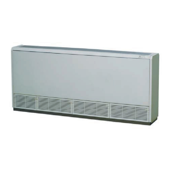
Page 11: Names Of Parts
Names of Parts Floor Exposed Type ● (H,Y,C)IFE 006B21S, 008B21S, 012B21S and 015B21S Name Remarks Fan Casing Fan Motor Heat Exchanger Electronic Expansion Valve Distributor Air Filter Refrigerant Gas Pipe Connection Refrigerant Liquid Pipe Connection Electrical Control Box Air Inlet Air Outlet Drain Pipe Connection φ3/4 inch (18.5mm) -
Page 12: Floor Concealed Type
Floor Concealed Type ● (H,Y,C)IFC 006B21S, 008B21S, 012B21S and 015B21S Name Remarks Fan Casing Fan Motor Heat Exchanger Electronic Expansion Valve Distributor Air Filter Refrigerant Gas Pipe Connection Refrigerant Liquid Pipe Connection Electrical Control Box Air Inlet Air Outlet Drain Pipe Connection φ3/4 inch (18.5mm) Wired Controller (Optional) The operating condition... -
Page 13: Wired Controller (Ciw01)
Wired Controller (CIW01) Following is an example of how the CIW01 is utilized. If other models of the controller are utilized, operate the unit according to the manual for that controller. The example below references the control panel and all adjustable settings. -
Page 14: Operation Method
Operation Method Basic Operation By pressing “ ”or “ ”, the icon “ ” moves between “MODE”, “SPEED”, Menu “LOUV.” and “TEMP”. Item Selection Back/Help With (“MODE”, “SPEED”, “LOUV.” or “TEMP”) selected, press “ ” or “ ”. Menu The setting is changed. Change of Settings Back/Help... -
Page 15: Cooling / Heating / Fan Mode
Cooling / Heating / Fan Mode Heating Mode is for VRF systems only and is not available for typical systems. Function * Cooling Mode: To decrease the room temperature. * Heating Mode: To increase the room temperature. * Dry Mode: To decrease the humidity in the room. -
Page 16: Temperature Setpoint
Temperature Setpoint Press “ ” or “ ” and select “TEMP”. Menu Back/Help By pressing “ ”, the temperature is increased by 1 F (0.5 C) to a Menu Max. 86 F (30 By pressing “ ”, the temperature is Back/Help decreased by 1 F (0.5... -
Page 17: Fan Speed
Fan Speed Press “ ” or “ ” and select “SPEED”. Menu Back/Help By pressing “ ” or “ ”, the fan speed is changed as follows. Menu Back/Help HIGH 2 HIGH AUTO ● During the dry mode, the fan speed automatically changes to “LOW” and you cannot change it to any other fan speed. -
Page 18: Automatic Heating/Cooling Operation
An automatic heating/cooling operation and setback operation requires extra settings. Contact your distributor or contractor for details. Automatic Heating/Cooling Operation In case dual setpoint is selected in automatic heating/cooling operation, during auto mode both cooling setpoint and heating setpoint can be selected. By default, temperature when the heating/cooling mode changes is as follows. -
Page 19: Automatic Control
Automatic Control This air conditioning unit automatically starts the following operations according to the indoor conditions. The system is equipped with the following functions. ▪ Enforced Stoppage: The compressor remains off for at least three minutes once it has stopped. If the system is started within approximately three minutes after it has stopped, the RUN indicator is activated. -
Page 20: Maintenance
Maintenance ● Turn OFF the power source before the maintenance work. If the power source is not turned OFF, the result may be an electric shock or fire. ● Perform the maintenance work with a stable foothold or foundation. This can prevent falling or injury. ●... - Page 21 (1) Removal of the air inlet grille and the air filter. (H,Y,C)IFE006B21S, 008B21S, 012B21S, and 015B21S • Loosen the screws of the securing plate on the right part of the grille. Then remove the plates. Press the knob on both sides of the grille in the direction indicated by the arrow. The grille can be opened at a 30 angle.
-
Page 22: Maintenance
(3) Attach the air inlet grille and the air filter. After the air filter is dried, attach it in the reverse order from what is shown in Step 1 above. NOTE ● Be sure to attach the air filter. Operating the indoor unit without a filter installed will cause serious damage and breakdown. ●... -
Page 23: Troubleshooting
Troubleshooting This is Normal Phenomenon Cause All indication lamps on the The micro-computer is activated to protect the wired controller are turned device from electromagnetic waves. Restart the OFF. operation. Operation Stopped Restart the operation. If the instantaneous power After Power Failure failure is within two seconds, the operation restarts automatically. -
Page 24: Before Contact
Before Contact Refer to the information below before contacting a contractor. Trouble Check Point Action Check that the main power Turn ON the main power source for the air source is turned ON. conditioner. Check that the fuse is not Operation Unavailable Replace the fuse or reset the circuit breaker. -
Page 25: Contact Distributor
Contact Distributor If trouble still persists, even after checking off previously listed items or detecting problems not mentioned in the previous pages, stop using this product and call your distributor or contractor immediately. If there is any perceived abnormality present (noises or odors associated with electrical short, fire, or burning elements), shut down immediately and shut OFF at the main power source. -
Page 26: Alarm Codes
Alarm Codes Code Category Content of Abnormality Code Category Content of Abnormality Indoor Unit Activation of Protection Device Incorrect Setting of Indoor Unit No. Activation of Protection Device Outdoor Unit System Incorrect Indoor Unit Combination (High Pressure Cut) Operational Irregularities between Problem with Protective Pickup Circuit Indoor and Outdoor in Outdoor Unit... - Page 28 © 2018 Johnson Controls, Inc. PMGB0375 Code No. LIT-12013023 Issued April 2018...
Need help?
Do you have a question about the HIFE006B21S and is the answer not in the manual?
Questions and answers