
Related Manuals for Johnson Controls HICM008B21S


Summary of Contents for Johnson Controls HICM008B21S
-
Page 1: Service Manual
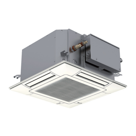
SERVICE MANUAL INVERTER-DRIVEN MULTI-SPLIT SYSTEM HEAT PUMP AIR CONDITIONERS Service Manual < Indoor Units > ● Mini Cassette (H,Y,C)ICM008B21S (H,Y,C)ICM012B21S (H,Y,C)ICM015B21S (H,Y,C)ICM018B21S SM-18003... -
Page 3: Important Notice
Important Notice ● Johnson Controls Inc. pursues a policy of continuing improvement in design and performance in its products. As such, Johnson Controls Inc. reserves the right to make changes at any time without prior notice. ● Johnson Controls Inc. cannot anticipate every possible circumstance that might involve a potential hazard. ● This heat pump air conditioning unit is designed for standard air conditioning applications only. Do not use this unit for anything other than the purposes for which it was intended for. ● The installer and system specialist shall safeguard against leakage in accordance with local pipefitter and electrical codes. The following standards may be applicable, if local regulations are not available. International Organization for Standardization: (ISO 5149 or European Standard, EN 378). No part of this manual may be reproduced in any way without the expressed written consent of Johnson Controls Inc. ● This heat pump air conditioning unit will be operated and serviced in the United States of America and comes with a full complement of the appropriate Safety, Danger, and Caution, warnings. ● If you have questions, please contact your distributor or dealer. ● This manual provides common descriptions, basic and advanced information to maintain and service this heat pump air conditioning unit which you operate as well for other models. ● This heat pump air conditioning unit has been designed for a specific temperature range. For optimum performance and long life, operate this unit within the range limits. ● This manual should be considered as a permanent part of the air conditioning equipment and should remain with the air conditioning equipment. SM-18003... - Page 4 Product Inspection upon Arrival 1. Upon receiving this product, inspect it for any damages incurred in transit. Claims for damage, either apparent or concealed, should be filed immediately with the shipping company. 2. Check the model number, electrical characteristics (power supply, voltage, and frequency rating), and any accessories to determine if they agree with the purchase order. 3. The standard utilization for this unit is explained in these instructions. Use of this equipment for purposes other than what it designed for is not recommended. 4. Please contact your local agent or contractor as any issues involving installation, performance, or maintenance arise. Liability does not cover defects originating from unauthorized modifications performed by a customer without the written consent of Johnson Controls, Inc. Performing any mechanical alterations on this product without the consent of the manufacturer will render your warranty null and void. SM-18003...
-
Page 5: Important Safety Instructions
1. Introduction This Service Manual concentrates on the heat pump air conditioning units. Read this manual carefully before performing service. This manual should be considered as a permanent part of the air conditioning equipment and should remain with the air conditioning equipment. (Transportation/Installation Work) > (Refrigerant Piping Work) > (Electrical Wiring Work) > (Ref. Charge Work) > (Test Run) > (User) 2. Important Safety Instructions Signal Words Indicates a hazardous situation that, if not avoided, could result in death or serious injury. Indicates a hazardous situation that, if not avoided, could result in minor or moderate injury. Indicates information considered important, but not hazard-related (for example, messages relating to property damage). General Precautions To reduce the risk of serious injury or death, read these instructions thoroughly and follow all warnings or cautions included in all manuals that accompanied the product and are attached to the unit. Refer back to these instructions as needed. ● This system should be installed by personnel certified by Johnson Controls, Inc. Personnel must be qualified according to local, state and national building and safety codes and regulations. Incorrect installation could cause leaks, electric shock, fire or explosion. In areas where Seismic ‘’Performance requirements are specified, the appropriate measures should be taken during installation to guard against possible damage or injury that might occur in an earthquake if the unit is not installed correctly, injuries may occur due to a falling unit. ● Use appropriate Personal Protective Equipment (PPE), such as gloves and protective goggles and, where appropriate, have a gas mask nearby. Also use electrical protection equipment and tools suited for electrical operation purposes. Keep a wet cloth and a fire extinguisher nearby during brazing. Use care in handling, rigging, and setting of bulky equipment. ● When transporting, be careful when picking up, moving and mounting these units. Although the unit may be packed using plastic straps, do not use them for transporting the unit from one location to another. Do not stand on or put any material on the unit. Get a partner to help, and bend with your knees when lifting to reduce strain on your back. Sharp edges or thin aluminum fins on the air... - Page 6 Take the following precautions to reduce the risk of property damage. ● Be careful that moisture, dust, or variant refrigerant compounds not enter the refrigerant cycle during installation work. Foreign matter could damage internal components or cause blockages. ● If air filters are required on this unit, do not operate the unit without the air filter set in place. If the air filter is not installed, dust may accumulate and breakdown may result. ● Do not install this unit in any place where silicon gases can coalesce. If the silicon gas molecules attach themselves to the surface of the heat exchanger, the finned surfaces will repel water. As a result, any amount of drainage moisture condensate can overflow from the condensate pan and could run inside of the electrical box, possibly causing electrical failures. ● When installing the unit in a hospital or other facility where electromagnetic waves are generated from nearby medical and/or electronic devices, be prepared for noise and electronic interference Electromagnetic Interference (EMI). Do not install where the waves can directly radiate into the electrical box, controller cable, or controller. Inverters, appliances, high-frequency medical equipment, and radio communications equipment may cause the unit to malfunction. The operation of the unit may also adversely affect these same devices. Install the unit at least 10 ft. (approximately 3m) away from such devices. ● When a wireless controller is used, locate at a distance of at least 3.3 ft. (approximately 1m) between the indoor unit and electric lighting. If not, the receiver part of the unit may have difficulty receiving operation commands. ● Do not install the unit in any location where animals and plants can come into direct contact with the outlet air stream. Exposure could adversely affect the animals and plants. ● Do not install the unit with any downward slope to the side of the condensate pipe. If you do, you may have drain water flowing back which may cause leaks. ● Be sure the condensate hose discharges water properly. If connected incorrectly, it may cause leaks. ● Do not install the unit in any place where oil can seep onto the units, such as table or seating areas in restaurants, and so forth. For these locations or social venues, use specialized units with oil-resistant features built into them. In addition, use a specialized ceiling fan designed for restaurant use. These specialized oil-resistant units can be ordered for such applications. However, in places where large quantities of oil can splash onto the unit, such as a factory, even the specialized units cannot be used. These products should not be installed in such locations. ● If the wired controller is installed in a location where electromagnetic radiation is generated, make sure that the wired controller is shielded and cables are sleeved inside conduit tubing.
-
Page 7: Installation Precautions
Installation Precautions To reduce the risk of serious injury or death, the following installation precautions must be followed. ● When installing the unit into… ◦ A wall: Make sure the wall is strong enough to hold the unit’s weight. It may be necessary to construct a strong wood or metal frame to provide added support. ◦ A room: Properly insulate any refrigerant tubing run inside a room to prevent “sweating” that can cause dripping and water damage to wall and floors. ◦ Damp or uneven areas: Use a raised concrete pad or concrete blocks to provide a solid, level foundation for the unit to prevent water damage and abnormal vibration. ◦ An area with high winds: Securely anchor the outdoor unit down with bolts and a metal frame. Provide a suitable wind baffle. ◦ A snowy area: Install the outdoor unit on a raised platform that is higher than drifting snow. Provide snow protection hood. ● If the remote sensors are not used with this controller, then do not install this controller… ◦ in a room where there is no thermostat. ◦ where the unit is exposed to direct sunshine or direct light. ◦ where the unit will be in close proximity to a heat source. ◦ where hot/cold air from the outdoors, or a draft from elsewhere (such as air vents, diffusers or grilles) can affect air circulation. ◦ in areas with poor air circulation and ventilation. ● Do not install the unit in the following places. Doing so can result in an explosion, fire, deformation, corrosion, or product failure. ◦ Explosive or flammable atmosphere. ◦ Where fire, oil, steam, or powder can directly enter the unit, such as in close proximity or directly above a kitchen stove. -
Page 8: Refrigerant Precautions
Refrigerant Precautions To reduce the risk of serious injury or death, the following refrigerant precautions must be followed. ● As originally manufactured, this unit contains refrigerant installed by Johnson Controls. Johnson Controls uses only refrigerants that have been approved for use in the unit’s intended home country or market. Johnson Controls distributors similarly are only authorized to provide refrigerants that have been approved for use in the countries or markets they serve. The refrigerant used in this unit is identified on the unit’s faceplate and/or in the associated manuals. Any additions of refrigerant into this unit must comply with the country’s requirements with regard to refrigerant use and should be obtained from Johnson Controls distributors. Use of any non-approved refrigerant substitutes will void the warranty and will increase the potential risk of injury or death. ● If installed in a small room, take measures to prevent the refrigerant from exceeding the maximum allowable concentration in the event that refrigerant gases should escape. The installation should meet the requirements in ASHRAE Standards 15 and 34. If refrigerant gas has leaked during the installation work, ventilate the room immediately. ● Check the design pressure for this product is 601 psi (4.15MPa). The pressure of the refrigerant R410A is 1.4 times higher than that of the refrigerant R22. Therefore, the refrigerant piping for R410A shall be thicker than that for R22. Make sure to use the specified refrigerant piping. If not, the refrigerant piping may rapture due to an excessive refrigerant pressure. Besides, pay attention to the piping thickness when using copper refrigerant piping. The thickness of copper refrigerant piping differs depending on its material. ● The refrigerant R410A is adopted. The refrigerant oil tends to be affected by foreign matters such as moisture, oxide film, (or fat). Perform the installation work with care to prevent moisture, dust, or different refrigerant from entering the refrigerant cycle. Foreign matter can be introduced into the cycle from such parts as expansion valve and the operation may be unavailable. ● To avoid the possibility of different refrigerant or refrigerant oil being introduced into the cycle, the sizes of the charging connections have been changed from R407C type and R22 type. It is necessary to prepare the appropriate tools before performing installation work. ● Use refrigerant pipes and joints which are approved for use with R410A. ● A compressor/unit comprises a pressurized system. Never loosen threaded joints while the system is under pressure and never open pressurized system parts. ● Before installation is complete, make sure that the refrigerant leak test has been performed. If refrigerant gases escape into the air, turn OFF the main switch, extinguish any open flames and contact your service contractor. Refrigerant (Fluorocarbon) for this unit is odorless. If the refrigerant... - Page 9 Electrical Precautions Take the following precautions to reduce the risk of electric shock, fire or explosion resulting in serious injury or death. ● Highly dangerous electrical voltages are used in this system. Carefully refer to the wiring diagram and these instructions when wiring. Improper connections and inadequate grounding can cause serious injury or death. ● Perform all electrical work in strict accordance with this manual and all the relevant regulatory standards. ● Before servicing, open and tag all disconnect switches. Never assume electrical power is disconnected. Check with meter and equipment. ● Only use electrical protection equipment and tools suited for this installation. ● Insulate a wired controller against moisture and temperature extremes. ● Use specified cables between units. ● The new air conditioner may not function normally in the following instances: ◦ If electrical power for the new air conditioner is supplied from the same transformer as the external equipment* referred to below. ◦ If the power supply cables for this external equipment* and the new air conditioner unit are located in close proximity to each other. external equipment*: (Example): A lift, container crane, rectifier for electric railway, inverter power device, arc furnace, electric furnace, large-sized induction motor and large-sized switch. Regarding the cases mentioned above, surge voltage may be inducted into the power supply cables for the packaged air conditioner due to a rapid change in power consumption of the device and an activation of a switch. Check field regulations and standards before performing electrical work in order to protect the power supply for the new air conditioner unit. ● Communication cabling shall be a minimum of AWG18 (0.82mm ), 2-Conductor, Stranded Copper. Shielded cable must be considered for applications and routing in areas of high EMI and other sources of potentially excessive electrical noise to reduce the potential for communication errors.
- Page 10 viii SM-18003...
-
Page 11: Table Of Contents
- Table of Contents - 1. Installation ..........................1-1 1.1 Outdoor Unit ............................1-2 1.2 Change-Over Box..........................1-2 1.3 Indoor Unit ............................1-2 1.4 Control Device ..........................1-3 1.4.1 Wired Controller: CIW01 ......................1-3 1.4.2 Simplified Wired Controller: CIS01 ..................1-3 1.4.3 Wireless Controller: CIR01 .....................1-3 1.4.4 Mini Central Controller: CCM01 .....................1-3 1.4.5 Large Central Controller: CCL01....................1-3 1.4.6 Computerized Central Controller Management Software: CCCS01 ........1-3 1.4.7 Computerized Central Controller Software / Operation Ratio for CCCS01 ......1-3 1.4.8 Computerized Central Controller Adapter: CCCA01 ..............1-3 1.4.9 Infrared (IR) Receiver Kit: CMIRK01 . - Page 12 - Table of Contents - 3. Troubleshooting ........................3-1 3.1 Initial Troubleshooting ........................3-2 3.1.1 Checking Electrical Wiring and Power Supply ...............3-2 3.1.2 Location of Printed Circuit Boards (PCBs) ................3-6 3.1.3 Checking Rotary Switch and DIP Switch Settings ..............3-7 3.1.4 Checking Wired Controller .....................3-9 3.1.5 Checking Using 7-Segment Display..................3-15 3.1.6 Checking Alarm Code History ....................3-15 3.1.7 Emergency Operation ......................3-15 3.2 Troubleshooting Procedures ......................3-16 3.2.1 Alarm Code Table ........................3-17 3.2.2 Troubleshooting Using Alarm Codes ..................3-18 3.2.3 Abnormalities of Devices ......................3-33 3.3 Procedures for Checking .........................3-45 3.3.1 Self-Checking of PCBs using Wired Controller ..............3-45 3.3.2 Self-Checking of Wired Controller .
- Page 13 - Table of Contents - 4. Maintenance ..........................4-1 4.1 Maintenance of Outdoor Unit ......................4-2 4.2 Maintenance of Indoor Unit ......................4-3 4.2.1 Removing Air Filter and Air Inlet Grille ...................4-3 4.2.2 Removing Electrical Box Cover ....................4-4 4.2.3 Removing Optional Decorative Panel ..................4-5 4.2.4 Removing Turbo Fan and Fan Motor ..................4-7 4.2.5 Removing Printed Circuit Board .....................4-8 4.2.6 Removing Drain Pan ......................4-9 4.2.7 Removing Drain-up Mechanism .....................4-10 4.2.8 Removing Float Switch ......................4-11 4.2.9 Removing Outlet Air Thermistor .....................4-12 4.2.10 Removing Liquid Pipe Thermistor, Gas Pipe Thermistor and Expansion Valve Coil.....4-13 4.2.11 Removing Inlet Air Thermistor ....................4-15 4.2.12 Removing Auto Louver Motors and Louver .
- Page 14 - Table of Contents - 5. External Input/Output and Function Setting ................5-1 5.1 DIP Switch Settings of Outdoor Unit ....................5-2 5.2 High Static Pressure Setting (DSW5-No.5: ON) ................5-2 5.3 External Input/Output and Function Setting Mode for Outdoor Unit ..........5-2 5.4 External Input/Output and Function Setting Mode for Indoor Unit ..........5-3 5.4.1 External Input and Output Settings ..................5-5 5.4.1.1 Remote Control ON/OFF Function ...................5-6 5.4.1.2 Power Supply ON/OFF 1 (Automatic Operation When Power Supply Is ON) ....5-11 5.4.1.3 Power Supply ON/OFF 2 (Restarting Function After Power Failure) ........5-11 5.4.1.4 Control by Field-Supplied Room Thermostat [ Input Setting: Code (01) (for Cooling), Code (02) (for Heating) ] ........5-12 5.4.1.5 Remote Cooling/Heating Change [ Input Setting: Code (07) ] ..........5-13 5.4.1.6 Picking Up Operation Signal .....................5-14 5.4.2 Function Setting ........................5-17 5.4.2.1 Function Selection Item ....................5-17 5.4.2.2 Description of Function Selection Item ................5-23 5.5 Functions from Wired Controller......................5-36 5.5.1 Power Saving Function ......................5-36 5.5.2 Schedule Function .........................5-38...
-
Page 15: Installation
INSTALLATION 1. Installation SM-18003... -
Page 16: Outdoor Unit
INSTALLATION 1.1 Outdoor Unit Refer to the Installation Manual for Outdoor Unit. 1.2 Change-Over Box Refer to the Installation Manual for Change-Over Box. 1.3 Indoor Unit Refer to the Installation Manual for Mini Cassette and Decorative Panel. SM-18003... -
Page 17: Control Device
INSTALLATION 1.4 Control Device 1.4.1 Wired Controller: CIW01 1.4.2 Simplified Wired Controller: CIS01 1.4.3 Wireless Controller: CIR01 1.4.4 Mini Central Controller: CCM01 1.4.5 Large Central Controller: CCL01 1.4.6 Computerized Central Controller Management Software: CCCS01 1.4.7 Computerized Central Controller Software / Operation Ratio for CCCS01 1.4.8 Computerized Central Controller Adapter: CCCA01 1.4.9... -
Page 18: Optional Parts
INSTALLATION 1.5 Optional Parts 1.5.1 Duct Adapter: PD-75C 1.5.2 Relay and 3 Pin Connector Kit: PSC-5RA 1.5.3 Remote Sensor: THM-R2A 1.5.4 3P Connector Cable: PCC-1A For more information of the above Optional Parts, please refer to the Installation Manuals for each product. SM-18003... -
Page 19: Operation
OPERATION 2. Operation SM-18003... -
Page 20: Indoor Unit
OPERATION 2.1 Indoor Unit Refer to the Operation Manual for Mini Cassette. SM-18003... -
Page 21: Control Device
OPERATION 2.2 Control Device 2.2.1 Wired Controller: CIW01 2.2.2 Simplified Wired Controller: CIS01 2.2.3 Mini Central Controller: CCM01 2.2.4 Large Central Controller: CCL01 2.2.5 Computerized Central Controller Management Software: CCCS01 2.2.6 Computerized Central Controller Software / Operation Ratio for CCCS01 2.2.7 Infrared (IR) Receiver Kit: CMIRK01 For more information of the above Control Devices, please refer to the Operation Manuals for each product. -
Page 23: Troubleshooting
TROUBLESHOOTING 3. Troubleshooting SM-18003... -
Page 24: Initial Troubleshooting
TROUBLESHOOTING 3.1 Initial Troubleshooting 3.1.1 Checking Electrical Wiring and Power Supply Check the following items if there is any abnormality in the activation of the system. Check Situation Check Method Is any power source breaker or Check the voltage (secondary side) of the breaker and also fuse open? check the continuity of the fuse with a tester. - Page 25 TROUBLESHOOTING ● For Outdoor Unit Refer to the Service Manual for Outdoor Unit. ● For Indoor Units The electrical wiring capacity of the outdoor unit is according to the “Installation and Maintenance Manual” of the outdoor unit. Setting DIP switches may be required depending on the combinations with the outdoor unit.
- Page 26 TROUBLESHOOTING NOTICE ● This equipment can be installed with a Ground Fault Circuit Interrupter (GFCI), which is a recognized measure for added protection to a properly grounded unit. Install appropriate sized breakers/ fuses/ overcurrent protection switches, and wiring in accordance with local, state and NEC codes and requirements.
- Page 27 TROUBLESHOOTING ● Wired Controller Connecting Diagram (a) Wired Controllers to each Unit for Individual Operation Setting Indoor Unit Indoor Unit Outdoor Unit Wired Wired Controller Controller (b) One Wired Controller for Individual Operation Setting Indoor Unit Indoor Unit Outdoor Unit Wired The communication cabling Controller...
-
Page 28: Location Of Printed Circuit Boards (Pcbs)
TROUBLESHOOTING 3.1.2 Location of Printed Circuit Boards (PCBs) (1) Outdoor Unit Refer to the Service Manual for Outdoor Unit. (2) Indoor Unit ● Mini Cassette PCB1 SM-18003... -
Page 29: Checking Rotary Switch And Dip Switch Settings
TROUBLESHOOTING 3.1.3 Checking Rotary Switch and DIP Switch Settings The following diagram indicates the factory settings of DSWs on PCBs in the indoor and outdoor units. When simultaneous operation control of multiple units or room thermo control is operated, the DSW setting will be different as shown below. - Page 30 TROUBLESHOOTING (5) Capacity Code Setting (DSW3) No setting is required because of the factory setting. This switch is utilized for setting the capacity code which corresponds to the capacity of the indoor unit. Indoor Unit Capacity (MBH) Setting Position 1 2 3 4 5 6 1 2 3 4 5 6 1 2 3 4 5 6 1 2 3 4 5 6...
-
Page 31: Checking Wired Controller
TROUBLESHOOTING 3.1.4 Checking Wired Controller Wired Controller Model: CIW01 Each “Check Menu” item and its function are explained in the following table. Check Menu Item Function Check 1 Sensor condition of air conditioner will be monitored and indicated. Check 2 Sensor data of air conditioner prior to alarm occurrence will be indicated. - Page 32 TROUBLESHOOTING Features of Check Mode 1 Item Data Name Item Data Name Set Temp. Suction Pressure Inlet Air Temp. Control Information Discharge Air Temp. Operating Frequency Liquid Pipe Temp. I.U. Capacity Remote Thermistor Temp. O.U. Code Outdoor Air Temp. System Number (1) Gas Pipe Temp.
- Page 33 TROUBLESHOOTING (2) Alarm History Display The Alarm History Display is accessed from the Check Menu. (1) Press and hold “Menu” and “ECO” simultaneously for 3 seconds during the normal Check Menu mode. Check 1 The Check Menu is displayed. Check 2 Alarm History Display (2) Select “Alarm History Display”...
- Page 34 TROUBLESHOOTING (3) I.U./O.U. PCB Check (1) Press and hold “Menu” and “ECO” simultaneously for three seconds during the Check Menu normal mode. I. U./O. U. PCB Check Check Menu is displayed. Self Checking (2) Select “I.U./O.U. PCB Check” from the Check Menu and press “OK”.
- Page 35 TROUBLESHOOTING (4) Self-Checking Self-Checking checks the wired controller and clears EEPROM (storage cell inside of the wired controller). (1) Press and hold “Menu” and “ECO” simultaneously for three seconds during the normal mode (when Check Menu unit is not operating). I.
- Page 36 TROUBLESHOOTING (9) No Function This function is not used. 07: No Function Press “OK” to proceed. 08: Transmission Test Self Checking 0 7 : 0 0 0 (10) Communication (Transmission) Circuit Test The wired controller automatically starts to check the communication circuit. (11) Wired Controller Thermistor Test The detected temperature by the wired controller Self Checking...
-
Page 37: Checking Using 7-Segment Display
TROUBLESHOOTING (5) Contact Information Registration Contact information can be registered from “Contact Information”. (1) Press and hold “Menu” and “Back/Help” simultaneously for at least three seconds during the normal mode (when unit is not operating). The Test Run Menu will be displayed. (2) Select “Contact Information”... -
Page 38: Troubleshooting Procedures
TROUBLESHOOTING 3.2 Troubleshooting Procedures l Alarm Code Indication of Wired Controller < CIW01 > (1) Refrigerant Cycle No. (*1) (1) (2) (2) Indoor Unit No. (*1) (3) Alarm Code 01-02 (4) Unit Model Code Alarm Code: (5) Total Number of Indoor Units in the Same System MODEL : F .08 AlarmRst as the Indoor Unit Having Trouble... -
Page 39: Alarm Code Table
TROUBLESHOOTING 3.2.1 Alarm Code Table Code Category Content of Abnormality Leading Cause Activation of Float Switch (High Water Level in Activation of Protection Device Indoor Unit Condensation Drainage Pan, Problem with Drain Piping, (Float Switch) Float Switch, or Condensation Drainage Pan) Operational Irregularities between Incorrect Wiring, Loose Terminals, Disconnect Wire, Communication... -
Page 40: Troubleshooting Using Alarm Codes
TROUBLESHOOTING 3.2.2 Troubleshooting Using Alarm Codes Alarm Activation of Protection Device (Float Switch) in Indoor Unit Code l The RUN indicator (red) flashes. l The indoor unit number (refrigerant cycle number - address number), the alarm code, the model code the model name and the number of connected indoor units are displayed on the LCD. - Page 41 TROUBLESHOOTING Action Event Cause Check Item (Turn OFF Main Switch) Clogging of Check drain pan. Activation of High Drain Drainage Remove foreign particles Check drainage by Float Switch Level Up-Slope clogging drain pipe. pouring water. Drain Piping Check continuity Replace float switch Failure when drain level is low.
- Page 42 TROUBLESHOOTING Alarm Abnormal Communication between Indoor Units and Outdoor Units Code l The RUN indicator (red) flashes. l The indoor unit number (refrigerant cycle number - address number), the alarm code, the model code the model name and the number of connected indoor units are displayed on the LCD, and the indoor unit number and the alarm code are displayed on the 7-segment display of the outdoor unit PCB.
- Page 43 TROUBLESHOOTING O.U. PCB: Outdoor Unit PCB I.U. PCB: Indoor Unit PCB Is voltage between Is LED1 (red) on "L1" and "N" of PCN1 Check Change-Over Change-Over Box on Change-Over Box Box wiring. PCB ON? PCB 208 or 230V? Is the fuse for Change-Over Box Replace fuse.
- Page 44 TROUBLESHOOTING Action Event Cause Check Item (Turn OFF Main Switch) Measure voltage with Power Failure or No Power Supply Supply power. tester. Remove cause of Check for breakage short circuit. Short Circuit between Wires of insulation. Replace fuse and/or I.U./O.U. PCB if faulty. Remove cause of short circuit to ground.
- Page 45 TROUBLESHOOTING 1: If the end terminal resistance (DSW10) is set to OFF for H-LINK connection, set the end terminal resistance to ON when CN2 is disconnected. Set the end terminal resistance to OFF when CN2 is reconnected. 2: 12VDC between VCC12 and GND2 5VDC between VCC05 and GND1 12VDC between VCC12 and GND1 15VDC between VCC15 and GND1...
- Page 46 TROUBLESHOOTING Abnormality of Thermistor for Indoor Unit Inlet Air Temperature Alarm Code (Inlet Air Thermistor) l The RUN indicator (red) flashes. l The indoor unit number (refrigerant cycle number - address number), the alarm code, the model code the model name and the number of connected indoor units are displayed on the LCD.
- Page 47 TROUBLESHOOTING Abnormality of Thermistor for Indoor Unit Outlet Air Temperature Alarm Code (Outlet Air Thermistor) l The RUN indicator (red) flashes. l The indoor unit number (refrigerant cycle number - address number), the alarm code, the model code the model name and the number of connected indoor units are displayed on the LCD.
- Page 48 TROUBLESHOOTING Abnormality of Thermistor for Liquid Refrigerant Pipe Temperature Alarm Code at Indoor Unit Heat Exchanger (Freeze Protection Thermistor) l The RUN indicator (red) flashes. l The indoor unit number (refrigerant cycle number - address number), the alarm code, the model code the model name and the number of connected indoor units are displayed on the LCD.
- Page 49 TROUBLESHOOTING Abnormality of Thermistor for Gas Refrigerant Pipe Temperature Alarm Code at Indoor Unit Heat Exchanger (Gas Pipe Thermistor) l The RUN indicator (red) flashes. l The indoor unit number (refrigerant cycle number - address number), the alarm code, the model code the model name and the number of connected indoor units are displayed on the LCD.
-
Page 50: Alarm Code
TROUBLESHOOTING Activation of Protection Device for Indoor Fan Motor Alarm Code (Indoor Unit with DC Motor) l The RUN indicator (red) flashes. l The indoor unit number (refrigerant cycle number - address number), the alarm code, the model code the model name and the number of connected indoor units are displayed on the LCD. - Page 51 TROUBLESHOOTING VCC13 LED5 VDC - VCC05 VCC15 PC4-#2 View from Backside of PCB Checking for Fan Motor Remove fan motor connector and measure the resistance value between each of the pins (twice, one measurement with +/- leads and the other with -/+ leads). Check whether the resistance value is over or not according to the table shown below.
- Page 52 TROUBLESHOOTING Alarm Incorrect Capacity Setting of Outdoor Unit and Indoor Unit Code l The RUN indicator (red) flashes. l The indoor unit number (refrigerant cycle number - address number), the alarm code, the model code the model name and the number of connected indoor units are displayed on the LCD. The alarm code is displayed on the 7-segment display of the outdoor unit PCB.
- Page 53 TROUBLESHOOTING Alarm Incorrect Indoor Unit No. Setting Code l The RUN indicator (red) flashes. l The indoor unit number (refrigerant cycle number - address number), the alarm code, the model code the model name and the number of connected indoor units are displayed on the LCD. The indoor unit number and the alarm code are displayed on the 7-segment display of the outdoor unit PCB.
- Page 54 TROUBLESHOOTING Alarm Incorrect Setting of Unit Model Code Code l The RUN indicator (red) flashes. l The indoor unit number (refrigerant cycle number - address number), the alarm code, the model code the model name and the number of connected indoor units are displayed on the LCD. The indoor unit number and the alarm code are displayed on the 7-segment display of the outdoor unit PCB.
-
Page 55: Abnormalities Of Devices
TROUBLESHOOTING 3.2.3 Abnormalities of Devices Other Abnormalities of Devices Abnormalities If there is no abnormality (Alarm Code) indicated on the wired controller, and normal operation is not available, take necessary action according to the following procedures. Action Phenomenon Cause Check Item (Turn OFF Main Switch) Disconnected Measure coil... - Page 56 TROUBLESHOOTING Other Abnormalities of Devices Abnormalities Action Event Cause Check Item (Turn OFF Main Switch) Check Setting Condition Check Setting Condition of "Thermistor of of "Thermistor of Wired Zone Controller" Wired Controller" with Optional Setting with Optional Setting * Setting and Control * Setting and Control "00": Control by Indoor "00": Control by Indoor...
- Page 57 TROUBLESHOOTING Other Abnormalities of Devices Abnormalities Action Event Cause Check Item (Turn OFF Main Switch) Failure of Failure of Thermistor Replace or correctly Check Thermistor in Check thermistor in Discharge connect wires Self-Checking mode. self-checking mode *2). Air Temp. Disconnected if abnormal.
- Page 58 TROUBLESHOOTING Other Abnormalities of Devices Abnormalities Action Event Cause Check Item (Turn OFF Main Switch) Indoor Heat Load is Larger Calculate heat load. Use a larger unit. than Cooling Capacity Gas Leakage Correctly charge or Shortage Measure superheat. refrigerant after of Refrigerant repairing gas leakage.
- Page 59 TROUBLESHOOTING Other Abnormalities of Devices Abnormalities Action Event Cause Check Item (Turn OFF Main Switch) Check clogging of outdoor unit Remove clogging. heat exchanger. Obstacles at inlet or Insufficient outlet of outdoor unit Remove obstacles. Airflow to heat exchanger? Outdoor Unit Heat Secure sufficient Is service space for...
- Page 60 TROUBLESHOOTING Other Abnormalities of Devices Abnormalities Action Event Cause Check Item (Turn OFF Main Switch) Communication Check indoor unit Failure Repair it according indicating alarm code between to alarm code “03”. “03” on wired controller. I.U. and O.U. Insufficient Check indoor unit Check wired controller Communication Power...
- Page 61 TROUBLESHOOTING Other Abnormalities of Devices Abnormalities Action Event Cause Check Item (Turn OFF Main Switch) Indoor Heat Load is Larger Use larger unit. Calculate heat load. than Heating Capacity Gas Leakage Correctly charge or Insufficient refrigerant after gas Measure superheat. Refrigerant leakage check and Charge...
- Page 62 TROUBLESHOOTING Other Abnormalities of Devices Abnormalities Action Event Cause Check Item (Turn OFF Main Switch) Communication Check indoor unit Failure Repair it according indicating alarm code between to alarm code “03”. “03” on wired controller. I.U. and O.U. Insufficient Check indoor unit Check wired controller Communication Power...
- Page 63 TROUBLESHOOTING Other Abnormalities of Devices Abnormalities Action Event Cause Check Item (Turn OFF Main Switch) Check for filter clogging. Remove clogging. Insufficient Airflow to Check for any obstacles Indoor Unit at inlet or outlet of Remove obstacles. Heat indoor unit. Exchanger Check indoor fan speed.
- Page 64 TROUBLESHOOTING Other Abnormalities of Devices Abnormalities Action Event Cause Check Item (Turn OFF Main Switch) Foreign Particles Inside Remove foreign Check it by viewing. Fan Casing particles. Indoor Unit Fan Wheel Adjust position of Check it by viewing. Contacts Casing fan wheel.
- Page 65 TROUBLESHOOTING Abnormalities of Devices Other (Motion and Radiation Sensor) Abnormalities Action Event Cause Check Item (Turn OFF Main Switch) True: Replace motion Check the “Check Mode 1: and radiation sensors q1” on the wired controller. “Motion Sensor PCB. is activated” is Reaction rate is always ↓...
- Page 66 TROUBLESHOOTING Abnormalities of Devices Other (Motion and Radiation Sensor) Abnormalities Action Event Cause Check Item (Turn OFF Main Switch) Immediately after True: No problem. “Radiation Sensor is This control targets the activated” indication on setpoint on the wired wired controller LCD, controller with heating check the “Check Mode 1: operation.
-
Page 67: Procedures For Checking
TROUBLESHOOTING 3.3 Procedures for Checking 3.3.1 Self-Checking of PCBs using Wired Controller Refer to Section 3.1.4 “Checking Wired Controller” 3.3.2 Self-Checking of Wired Controller Refer to Section 3.1.4 “Checking Wired Controller” 3-45 SM-18003... -
Page 68: Test Run
TROUBLESHOOTING 3.4 Test Run Turn OFF all the power supply switches. Use a tester and make sure that all the switches are turned OFF. Before the test run, check that the unit is appropriately installed according to the Installation and Maintenance Manual. -
Page 69: Test Run Using Wired Controller
TROUBLESHOOTING 3.4.1 Test Run Using Wired Controller (1) Wired Controller (CIW01) Menu Menu Button On/Off (1) Turn ON the power source of the indoor and outdoor units. Back/Help ECO (2) Set the TEST RUN mode with the wired zone controller. (2) Set the TEST RUN mode with the wired controller. - Page 70 TROUBLESHOOTING (4) Press “On/Off” switch. button. Normal The test run operation will be started. The operation mode, the airflow volume, the airflow direction The run test operation will be started. The operation mode, the airflow volume, the airflow direction and the test run time can be set on the Test Run screen. and the run test time can be set on the Test Run screen.
-
Page 71: Test Run From Outdoor Unit Side
TROUBLESHOOTING 3.4.2 Test Run from Outdoor Unit Side Refer to the Service Manual for Outdoor Unit. 3.4.3 Checking the Test Run < Voltage Change > Initial Voltage (1) Indoor and Outdoor Fan Operating Voltage Check that the indoor fan and outdoor fan rotate correctly and the airflow is smooth. -
Page 72: Check List For Refrigerant System
TROUBLESHOOTING (b) When the high pressure retry control is activated, alarm code “ ” will be indicated on the 7-segment display of the outdoor unit PCB. If the high pressure retry control occurs three times or more within 30 minutes, alarm code “ ”... -
Page 73: Maintenance
MAINTENANCE 4. Maintenance SM-18003... -
Page 74: Maintenance Of Outdoor Unit
MAINTENANCE 4.1 Maintenance of Outdoor Unit Refer to the Service Manual for Outdoor Unit. SM-18003... -
Page 75: Maintenance Of Indoor Unit
MAINTENANCE 4.2 Maintenance of Indoor Unit Use the specified non-flammable refrigerant (R410A) to the outdoor unit in the refrigerant cycle. Do not charge the unit with materials other than R410A, such as hydrocarbon refrigerants (propane, etc.), oxygen, flammable gases (acetylene, or etc.) or poisonous gases when installing, maintaining and moving the unit. -
Page 76: Removing Electrical Box Cover
MAINTENANCE TURN OFF all power source switches. Take care not to drop the electrical box cover. 4.2.2 Removing Electrical Box Cover (1) The electrical box appears when opening the air inlet grille. Loosen 2 fixing screws for the electrical box cover and open the electrical box. Tool Phillips Screwdriver Slide the electrical box cover downward to remove. Electrical Box Electrical Box Cover Fixing Screws for Electrical Box Cover Loosen the fixing screws to remove the electrical box cover. -
Page 77: Removing Optional Decorative Panel
MAINTENANCE TURN OFF all power source switches. 4.2.3 Removing Optional Decorative Panel (1) Remove the auto swing motor connector (CN17) from PCB. (2) Remove the corner pocket covers. The corner pocket covers can be removed pulling "A" part toward the arrow direction in the figure below. Tool Phillips Screwdriver Electrical Box CN17 SM-18003... - Page 78 MAINTENANCE TURN OFF all power source switches. (3) Remove the long screws of A at the decorative panel. Loosen the long screws of B and rotate the decorative panel according to the arrow direction to remove the decorative panel. Tool Phillips Screwdriver Refrigerant Pipe Indoor Unit Electrical Box Fixing Plate (Indoor Unit) Indication Mounting “PIPE SIDE” Sheet Decorative Panel Long Screw (Qty: 4pcs.) SM-18003...
-
Page 79: Removing Turbo Fan And Fan Motor
MAINTENANCE TURN OFF all power source switches. 4.2.4 Removing Turbo Fan and Fan Motor (1) Remove the air inlet grille according to Section 4.2.1 “Removing Air Filter and Air Inlet Grille.” (2) Removing Bell-mouth Remove 4 fixing screws for the bell-mouth fixed to the drain pan, and remove the bell-mouth. (3) Removing the Fan Guide Remove the 8 fixing screws for the fan guide and remove the fan guide. (4) Removing Turbo Fan and Fan Motor (a) Remove the nut fixing the fan runner. (b) Remove 3 nuts fixing the fan motor. -
Page 80: Removing Printed Circuit Board
MAINTENANCE TURN OFF all power source switches. 4.2.5 Removing Printed Circuit Board (1) Remove the electrical box cover according to Section 4.2.2 “Removing Electrical Box Cover.” (2) Disconnect all wire connectors from the indoor unit PCB. (3) Remove the screw for earth wire. (4) Remove the screw then remove the PCB cover. (5) The indoor unit PCB is fixed by 6 holders. Pull out PCB from each holder as shown in the figure. Tool Phillips Screwdriver, Long-nose Plier Pull out PCB Holder Holder Push Holder Electrical Box Electrical Box PCB Cover Pinch here with long-nose piler to remove PCB. Holder Electrical Box NOTES:... -
Page 81: Removing Drain Pan
MAINTENANCE TURN OFF all power source switches. 4.2.6 Removing Drain Pan (1) Remove the decorative panel according to Section 4.2.3 “Removing Optional Decorative Panel.” (2) Remove the screw then remove the wire cover. (3) Remove the electrical box cover according to Section 4.2.2 “Removing Electrical Box Cover.” Disconnect the connectors of the gas pipe thermistor, the liquid pipe thermistor, the expansion valve and the fan motor. (4) Remove the bell-mouth according to Section 4.2.4 “Removing Turbo Fan and Fan Motor.” (5) Draining Water (a) Pull out the rubber plug from the drain pan, and drain the water remaining in the drain pan. Although silicon sealant is applied over the rubber plug, the rubber plug can be removed by pulling the bottom side. NOTE: 1. Do not damage the rubber plug with a cutter. 2. Do not damage or remove the insulation attached to the bottom side of the rubber plug when removing/attaching it (b) Check any clogging in the drain hole. (6) Removing Drain Pan (a) Remove 4 screws fixing the drain pan to the unit. (b) Then lift the drain pan down to remove it from the unit. Phillips Screwdriver, Tool Bucket (with an approx. 5 liter capacity) -
Page 82: Removing Drain-Up Mechanism
MAINTENANCE TURN OFF all power source switches. 4.2.7 Removing Drain-up Mechanism (1) Remove the drain pan according to Section 4.2.6 “Removing Drain Pan.” (2) Remove the lead wires for the drain up mechanism, float switch and outlet air thermistor gathered with vinyl tube and clamping band (Do not dispose the vinyl tube). (3) Cut the plastic band and disconnect the drain hose from the drain-up mechanism. (4) Remove the fixing screw for the drain-up mechanism. Make sure to hold the drain-up mechanism by hand so that it will not fall off. (5) Then remove the drain-up mechanism. Tool Phillips Screwdriver Plastic Band Drain Hose Float Switch Fixing Screw for Float Switch Drain-up Mechanism Fixing Screw for Drain-up Mechanism (3 pcs) Fixing Base of Drain-up Mechanism Drain Hose Disconnect the drain hose... -
Page 83: Removing Float Switch
MAINTENANCE TURN OFF all power source switches. 4.2.8 Removing Float Switch (1) Remove the drain pan according to Section 4.2.6 “Removing Drain Pan.” (2) Remove the lead wires for the drain up mechanism, float switch and outlet air thermistor according to Section 4.2.7 "Removing Drain-up Mechanism" (3) Removing Float Switch (a) The float switch is attached to the drain pan. Remove the fixing screw and remove the fixing plate for the float switch from the drain pan. (b) Loosen the resin nut for the float switch and remove the float switch from the fixing plate. Tool Phillips Screwdriver, Nipper Drain-up Mechanism Float Switch Fixing Plate Fixing Screw for Drain-up Mechanism (3 pcs) Float Switch Fixing Screw for Float Switch... -
Page 84: Removing Outlet Air Thermistor
MAINTENANCE TURN OFF all power source switches. 4.2.9 Removing Outlet Air Thermistor (1) Remove the drain pan according to Section 4.2.6 “Removing Drain Pan.” (2) Remove the lead wires for the drain up mechanism, float switch and outlet air thermistor according to Section 4.2.7 "Removing Drain-up Mechanism" (3) Removing the rubber plug then remove the outlet air thermistor from fixing base of drain up mechanism. Tool Phillips Screwdriver, Nipper Rubber Plug Outlet Air Thermistor Fixing Base of Drain-up Mechanism Drain-up Mechanism Float Switch Fixing Plate Fixing Screw Float Switch for Drain-up Mechanism (3 pcs) Fixing Screw for Float Switch 4-12... -
Page 85: Removing Liquid Pipe Thermistor, Gas Pipe Thermistor And Expansion Valve Coil
MAINTENANCE TURN OFF all power source switches. 4.2.10 Removing Liquid Pipe Thermistor, Gas Pipe Thermistor and Expansion Valve Coil (1) Remove the decorative panel according to Section 4.2.3 “Removing Optional Decorative Panel.” (2) Remove the bell-mouth and the fan runner according to Section 4.2.4 “Removing Turbo Fan and Fan Motor.” (3) Remove the drain pan according to Section 4.2.6 “Removing Drain Pan.” (4) Remove 5 screws for the partition plate fixing the heat exchanger. (5) Removing Thermistors (a) Remove butyl sheet attached to each thermistor. (b) Remove each thermistor for the gas pipe and the liquid pipe. NOTE: Each thermistor is fixed with a thermistor holder. (6) Removing Expansion Valve (a) Remove butyl sheet attached to the expansion valve. (b) Loosen the locknut using a wrench by turning it counterclockwise viewed from the expansion valve coil. NOTE: Remove the expansion valve coil with no pressure applied to it. Otherwise, the pressure would cause the bellows to pop up. Do not touch the bottom side of the drive part of the expansion valve coil when using a wrench. Otherwise, the bottom side of the drive part of the expansion valve coil starts to race and might be damaged. (7) Turn the locknut to remove the drive part from the expansion valve. Tool Phillips Screwdriver Fixing Screw (6 pcs) - Page 86 MAINTENANCE TURN OFF all power source switches. (8) Prepare a replacement drive part for the expansion valve coil. To make sure that the driver position has been adjusted, use a drive part specified as a service part. NOTE: 1. Be careful that dust and foreign matter will not enter the connection portion during replacement. The connection portion exposed due to replacement is the core of the expansion valve mechanism. 2. Do not damage the connection portion with tools, etc. (9) Attach the replacement drive part to the expansion valve and align their shafts. Then attach the locknut to the expansion valve. (10) Tighten the locknut to some degree by hand and then completely with the wrench. The tightening torque shall be 8.9 to 11.1 lbf·ft (12 to 15N·m). NOTE: Do not apply an excessive force to the expansion valve coil. The expansion valve coil is attached with its eccentricity facing the opposite side of the pipe joint. The direction does not affect the valve’s opening/closing action. Even if the position of the expansion valve coil is slightly misaligned after replacement, no adjustment with tools will be needed. NOTE: 1. After replacement, attach the gas pipe thermistor and the liquid pipe thermistor and the expansion valve coil in the reverse procedure. Attach butyl sheet to make sure that there is no clearance between the thermistors and butyl sheets. 2. After replacement, check that the wires do not contact the runner. 4-14 SM-18003...
-
Page 87: Removing Inlet Air Thermistor
MAINTENANCE TURN OFF all power source switches. 4.2.11 Removing Inlet Air Thermistor (1) Remove the inlet air thermistor connector (THM1) from fixing base. (2) Remove the bell-mouth according to Section 4.2.4 "Removing Turbo Fan and Fan Motor". (3) Tear off the filament tape then remove the thermistor cable attached to the bell-mouth. (4) Push the thermistor case cover to the direction shown in the picture below to remove the inlet air thermistor with the thermistor case cover. Tool Phillips Screwdriver Thermistor Cable with Filament Tape Thermistor Case Cover Bell-Mouth Bell-Mouth Thermistor Case Cover Pushing Direction 4-15 SM-18003... -
Page 88: Removing Auto Louver Motors And Louver
MAINTENANCE TURN OFF all power source switches. 4.2.12 Removing Auto Louver Motors and Louver (1) Remove the decorative panel according to Section 4.2.3 “Removing Optional Decorative Panel.” (2) Remove the fixing screw for C-cover and remove the C-cover. (3) Remove the fixing screw for AS Motor from the decorative panel. Then remove the louver, louver bearing and AS motor. (4) Remove the AS motor, stopper and bearing from the louver. (5) Disconnect the connector for the AS motor. Press the catch to disconnect the connector to avoid breakage. Tool Phillips Screwdriver Bearing C-Cover Screw Louver Decorative Panel Bearing Connector Decorative Panel AS Motor Louver Bearing Bearing AS Motor Stopper Air Inlet Side Pay attention to the... -
Page 89: Cleaning Indoor Unit Heat Exchanger
MAINTENANCE 4.3 Cleaning Indoor Unit Heat Exchanger 4.3.1 Required Tools for Cleaning (Field Supplied) Remark Tool Remark Cleaning Water Pump Water Tank Approx. 18 liters Clean Water A water pump equipped with Nozzle Attached with Water Pump a tank is recommended. Brush If the heat exchanger is heavily (non-metal) clogged with dust, remove it with this brush. The length of brush should be 1 to 1-3/8 inch (25 to 35mm). Hose for Select a hose according to site Drain Pan requirements. Bucket Approx. 5 liters (Qty: 2) Phillips Qty: 1 Screwdriver Pliers Qty: 1 Adjustable Qty: 1 Wrench Megohm Tester 500V... -
Page 90: Cleaning Procedure
MAINTENANCE TURN OFF all power source switches. 4.3.2 Cleaning Procedure Spread a vinyl sheet over the floor to protect furniture, etc. from cleaning water before this work. Procedure Tool Remove the optional decorative panel according to Section 4.2.3 "Removing Phillips Screwdriver Optional Decorative Panel." Remove the electrical box after opening the electrical box cover and disconnecting the connectors between the indoor and outdoor units and other Phillips Screwdriver connectors according to Section 4.2.2 "Removing Electrical Box Cover." Remove the bell-mouth and fan according to Section 4.2.4 "Removing Turbo Fan Phillips Screwdriver and Fan Motor." Adjustable Wrench Remove the drain pan according to Section 4.2.6 "Removing Drain Pan." Phillips Screwdriver Remove the float switch according to Section 4.2.9 "Removing Float Switch." Phillips Screwdriver Remove the drain-up mechanism according to Section 4.2.8 "Removing Drain-up Phillips Screwdriver Mechanism." NOTES: Remove the drain pan after removing drain water in the drain pan. 1. Remove the drain water in the drain pan after pulling out the rubber plug. 2. Insert the rubber plug into the hole after checking the above. 3. Remove the drain pan after removing four securing screws. Remove the drain pan carefully, since the drain water may remain at the bottom of the drain pan. 4. Clean and dry the drain pan after removing it. Handle the drain pan carefully so as not to damage it. 4-18 SM-18003... - Page 91 MAINTENANCE TURN OFF all power source switches. (1) Scratch off the dust on the inner surface of the heat exchanger downwards using a brush. Collect all dust in a bucket or box. Tool Brush, Bucket (or Box) (2) Attach a vinyl sheet around the heat exchanger by using adhesive tapes so that cleaning water will not be splashed over the insulation surface and drain-up pump. Seal the gap between vinyl sheets by using adhesive tapes. (3) Attach ropes to each suspension bracket. (4) Insert the bars through the holes of the cleaning water collector as shown in Section 4.3.1. (5) Attach the ropes to the four bars of the cleaning water collector and suspend the cleaning water collector as shown in the figure. (6) Connect the hose to the boss and put the end of the hose in a bucket. Tool Knife, Bucket Suspension Indoor Unit Bolt Rope Suspension The water collector Support Bracket should be located 13/16 to 1-3/16 inch Cleaning (8 Nos.)
- Page 92 MAINTENANCE TURN OFF all power source switches. (7) Put approximately 15 liters of cleaning agent for aluminum fins in the supply tank. Cleaning Agent for Aluminum Fins (8) Insert the spray nozzle into the hole of the cleaning water collector. Operate the water pump and clean the dust on the heat exchanger. After cleaning, spray clean water to remove the cleaning water. Adjust the pressure of the water pump so as not to damage the fins. Clean Water, Cleaning Agent, Tool Water Pump, Cleaning Spray Cleaning Spray Bucket NOTES: 1. If any cleaning water remains, fins will become corroded. 2. Adjust the pressure of the pump at 36 to 71 psi (2.5 to 5.0 kg/cm ) so as not to damage the fins. 4-20 SM-18003...
- Page 93 MAINTENANCE TURN OFF all power source switches. (9) After cleaning, mount the drain pan by extending the rope downwards. NOTE: When the cleaning water collector is removed, wipe off the drops from the indoor unit. Tool Phillips Screwdriver Drain Pan Cleaning Water Collector (10) Check the insulation of the drain pump with a megohm-meter. Check to ensure that the insulation is greater than 1 MΩ when 500V is applied. (11) Connect wiring as it was. (12) Neutralization Treatment after Cleaning The cleaning agent specified in Section 4.3.1 is of the neutral type. However, the cleaning water after use should not be neutral. Collect all cleaning water and provide necessary neutralization treatment for the cleaning water. 4-21 SM-18003...
-
Page 94: Main Parts
MAINTENANCE (Main Parts) 4.4 Main Parts 4.4.1 for Outdoor Unit Refer to the Service Manual for Outdoor Unit. 4.4.2 for Change-Over Box Refer to the Service Manual for Outdoor Unit. 4-22 SM-18003... -
Page 95: For Indoor Units
MAINTENANCE (Main Parts) 4.4.3 for Indoor Units 4.4.3.1 Printed Circuit Board ● Mini Cassette Arrangement of Connectors and Check Points for PCB1 (PI143) VCC13 CN33 CN14 THM5 THM3 THM2 THM1 CN36 GND VCC15 CN17 CN11 PCN7 4.4.3.2 Fan Motor ● Mini Cassette Rotating Direction 4-7/8 (123.5) 11/16 7-7/16 (61.8) (18.1) Enlarged View from P 8 7 6 5 4 3 2 1 Blue (PG) Yellow... -
Page 96: Thermistor
MAINTENANCE (Main Parts) 4.4.3.3 Thermistor (1) Position of Thermistor ● Mini Cassette Outlet Air Thermistor Liquid Pipe Thermistor Gas Pipe Thermistor (Freeze Protection) (THM2) (THM3) (THM5) Inlet Air Thermistor (THM1) (2) Thermistor for Indoor Suction Air Temperature (For Room Temperature Control) The room temperature is controlled by the Thermistor thermistor for indoor suction air temperature Resistance detecting the temperature at the suction air inlet of the indoor unit. 20.5 The setting temperature is indicated on 12.5... -
Page 97: Electronic Expansion Valve
MAINTENANCE (Main Parts) 4.4.3.4 Electronic Expansion Valve Micro-Computer Pulse Signal 2-Phase Permanent Magnetic Pulse Motor Control 0 to 2,000 Pulse by 1 Pulse Refrigerant Flow Control Precise Control Unit: inch (mm) φ1-9/16 Electronic Expansion (40) Valve Coil φ15/16 Model: PAM-MD12HS-4 (24.4) 35-7/16 13/16 (900 20) φ7/8 (21.85) - Page 98 MAINTENANCE (Main Parts) Specifications Items Specifications Type PAM Type Refrigerant Used R410A Working Temperature Range F to 158 F (-30 C to 70 Mounting Direction Drive Shaft in Vertical Direction, Motor Upside and 90 in Four Direction Flow Direction Reversible Drive Method 4-Phase Pulse Motor Method Rated Voltage DC12V+1.2V Drive Condition 100~250PPS 2 Phase Excitation Wiring Diagram, Drive Circuit White and Activation Mode Procedure Lead Wire φ1 Phase Color < COM > φ...
-
Page 99: External Input/Output And Function Setting
EXTERNAL INPUT/OUTPUT AND FUNCTION SETTING 5. External Input/Output and Function Setting SM-18003... -
Page 100: Dip Switch Settings Of Outdoor Unit
EXTERNAL INPUT/OUTPUT AND FUNCTION SETTING 5.1 DIP Switch Settings of Outdoor Unit Refer to the Service Manual for Outdoor Unit. 5.2 High Static Pressure Setting (DSW5-No.5: ON) Refer to the Service Manual for Outdoor Unit. 5.3 External Input/Output and Function Setting Mode for Outdoor Unit Refer to the Service Manual for Outdoor Unit. -
Page 101: External Input/Output And Function Setting Mode For Indoor Unit
EXTERNAL INPUT/OUTPUT AND FUNCTION SETTING 5.4 External Input/Output and Function Setting Mode for Indoor Unit ● Setting Method from Wired Controller The function selection and the input/output setting can be set from the test run menu. < Normal Mode Display > < Test Run Menu Display > Test Run Menu Meeting Room FLTR Test Run MODE SPEED LOUV. TEMP Function Selection COOL Thermistor Selection Input/Output LOUV. Adj. Elevating Grille Setting Menu Sel. - Page 102 EXTERNAL INPUT/OUTPUT AND FUNCTION SETTING ● Function Selection and Input/Output Setting 1. Press and hold “Menu” and “Back/Help” simultaneously Test Run Menu for at least three seconds during the normal mode Test Run (when unit is not operated). The Test Run menu will be displayed. Function Selection Thermistor Selection Input/Output 2. Select “Function Selection” or “Input/Output” from the Test Run menu and press “OK”. Elevating Grille Setting Sel. Entr Back Rtrn 3. Select the indoor unit by pressing “ ” and touch Function Selection “OK”. (This screen is NOT displayed when the number of an indoor unit connected with the controller is 01-01 "1". In this case, "4" will be displayed.)
-
Page 103: External Input And Output Settings
EXTERNAL INPUT/OUTPUT AND FUNCTION SETTING 5.4.1 External Input and Output Settings On the Indoor Unit Printed Circuit Board (PCB), there are two input terminals (CN3) to receive external signals and three output terminals (CN7, CN8) to send signals out. Functions shown in these tables are available when setting input and output terminals. < Input and Output Number Display and Connectors > Input Number Display Factory Setting Port Setting Input/Output Indication Setting Item Indication Input 1 CN3 1-2 Remote ON/OFF 1 (Level) Input 2 CN3 2-3 Prohibiting Remote Control after Manual Stoppage Output 1 CN7 1-2 Operation Output 2 CN7 1-3 Alarm Output 3 CN8 1-2 Thermo-ON for Heating < Input and Output Settings and Display Codes > Code Indicated Input Output... -
Page 104: Remote Control On/Off Function
EXTERNAL INPUT/OUTPUT AND FUNCTION SETTING 5.4.1.1 Remote Control ON/OFF Function This function provides a control to stop and start the system automatically from a remote place. Four methods are available by using each signal from a building management system. (1) Remote ON/OFF 1 (Level Signal Input) [ Input Setting: Code (03) ] This is an ON/OFF function from a remote place by using level signals (ON/OFF). An example of basic wiring and time chart is shown below. NOTE: When the unit is started by the remote ON/OFF switch, Indoor Unit PCB the fan speed is subject to the mode memorized in the wired controller. SS3: Remote ON/OFF Power Source... - Page 105 EXTERNAL INPUT/OUTPUT AND FUNCTION SETTING (2) Remote ON/OFF 2 (Pulse Signal Input) [ Input Setting: Code (04) ] This is an ON/OFF function from a remote place by using pulse signals. An example of basic wiring and time chart is shown below. Indoor Unit PCB NOTES: The pulse range shall be 200ms or more. Power Source Control Circuit 3P Connector Wiring Diagram Example of Remote ON/OFF 2 Example: Operation Input is set to terminals 2 and 3 of CN3. Stoppage Input is set to terminals 1 and 2 of CN3.
- Page 106 EXTERNAL INPUT/OUTPUT AND FUNCTION SETTING (3) Remote ON/OFF 3 (Pulse Signal Input) [ Input Setting: Code (05) ] The setting for Remote ON/OFF 3 shall be the same as that for Remote ON/OFF 2. By using the signal from a building management system, the indoor units can be stopped. If a signal is input during the stoppage of the indoor units, the unit remains unchanged. An example of basic wiring and time chart is shown below. NOTE: Indoor Unit PCB The pulse range shall be 200ms or more. Power Source Control Circuit 3P Connector Wiring Diagram Example of Remote ON/OFF 3 (Example: Stoppage Input is set to terminals 1 and 2 of CN3.) Signal to terminals 1 &...
- Page 107 EXTERNAL INPUT/OUTPUT AND FUNCTION SETTING (4) Forbidding Remote Control after Manual (Forced) Stoppage (Level Signal Input) [ Input Setting: Code (06) ] By using the signal from a building management system, the indoor units can be stopped and the individual commands from the wired controller are canceled. An example of basic wiring and time chart is shown below. Indoor Unit PCB SS3: Forced Stoppage Sw. Power Source 3P Connector Wiring Diagram Example Example: Forbidding Remote Control after Manual (Forced) Stoppage is set to terminals 2 and 3 of CN3. Signal to terminals 2 &...
- Page 108 EXTERNAL INPUT/OUTPUT AND FUNCTION SETTING Table 5.1 Specifications on Required Components for (1) to (4) Functions Component Manufacturer or Specifications Remarks OMRON Mini Power Relay Auxiliary Relay (X1, X2) Model: MY1F/2F or Equivalent Voltage 220V Changeover Switch (SS2, SS3) Manual Type Optional Part PCC-1A Five Cords with 3P Connector Cord (Connectable to JST Connector XARP-3), 12V Connectors as One Set Low Voltage AWG22 (0.3mm less than 12V Cord (Indoor) 220V Class AWG20 or AWG18 (0.5 to 0.75mm Low Voltage AWG20 or AWG18 (0.5 to 0.75mm less than 12V Cord (Outdoor) 220V Class AWG14 (2mm NOTE: 1. Make the wires CN3 as short as possible. Do not install the wires with the 220V power line. Install them more than 12 in. (30cm) away from each other. (Intersecting them is acceptable.) If the wires are installed along the power line, comply with the following points to prevent noise. a. Pass either of the low voltage wire and 220V power line through a metal conduit tube and ground one end. b. Use a shielded wire for a low voltage wire and ground one end. The maximum wiring length is 230 ft. (70m). 2. When using this function, it is recommended that safety devices such as an electric leakage breaker or smoke detector, etc., be used because this is an unattended function.
-
Page 109: Power Supply On/Off 1 (Automatic Operation When Power Supply Is On)
EXTERNAL INPUT/OUTPUT AND FUNCTION SETTING 5.4.1.2 Power Supply ON/OFF 1 (Automatic Operation When Power Supply Is ON) This function is utilized to run/stop the unit by turning ON/OFF the power supply. When this function is utilized in the condition that there is no person to operate the unit, monitor the system for disaster prevention. When using this function, refer to Section 5.4.2.2 "(30) Power Supply ON/OFF (Automatic Operation When Power Supply Is ON) (d1)" for the setting. NOTE: 1. The unit will be stopped even when the power supply is turned ON/OFF due to power failure. If power failure occurs during the stoppage of the unit, the operation is restarted after the power supply is restored. 2. Wired Controller is required for this function. 3. When the communication cable is not used in the twin, triple and quad combinations for simultaneous operation, set this function only to the main indoor unit. 5.4.1.3 Power Supply ON/OFF 2 (Restarting Function After Power Failure) This function is utilized to restart the unit operation automatically when the power supply is restored after the power failure over 2 seconds. In case of the power failure for 2 seconds or less, the standard unit memorize all the operation mode and restarts the operation automatically. (The compressor restarts operation after 3 minutes guard in addition to power failure time for up to 2 seconds.) When this function is utilized in the condition that there is no person to operate the unit, monitor the system for disaster prevention. When using this function, refer to Section 5.4.2.2 "(32) Power Supply ON/OFF (Restarting Function after Power Failure) (d3)" for setting. NOTE: 1. If power failure occurs during the stoppage of the unit, the unit remains stopped after the power supply is restored. 2. Wired Controller is required to be connected for setting this function. 3. When the communication cable is not used in the twin, triple and quad combinations for simultaneous operation, set this function only to the main indoor unit. 5-11 SM-18003... -
Page 110: Control By Field-Supplied Room Thermostat [ Input Setting: Code (01) (For Cooling), Code (02) (For Heating) ]
EXTERNAL INPUT/OUTPUT AND FUNCTION SETTING 5.4.1.4 Control by Field-Supplied Room Thermostat [ Input Setting: Code (01) (for Cooling), Code (02) (for Heating) ] In a case where a field-supplied room thermostat is used instead of the inlet thermistor of the indoor unit in order to run/stop the compressor, connect wires as shown below. 3P Connector Thermostat NOTE: The contact capacity of a thermostat shall be DC12V and several mA. Select a thermostat which makes and breaks the Temperature contact with this capacity. Increase Indoor Unit PCB Field-Supplied Room Thermostat Example: Room Thermostat Input (for Cooling) is set to terminals 2 and 3 of CN3... -
Page 111: Remote Cooling/Heating Change [ Input Setting: Code (07) ]
EXTERNAL INPUT/OUTPUT AND FUNCTION SETTING 5.4.1.5 Remote Cooling/Heating Change [ Input Setting: Code (07) ] The cooling or heating operation mode can be changed by giving a contact signal from the outside to the unit. Set this function to CN3 with a wired controller according to Section 5.4.2.1 “Function Selection Item.” This function detects ON to OFF transition and OFF to ON transition. Of the commands by this signal and a wired controller, the command given later is preferentially executed. An example of basic wiring and time chart is shown below. Indoor Unit PCB HEAT COOL Power Source 3P Connector Wiring Diagram Example (Example: Remote Cooling/Heating Change is set to terminals 1 and 2 of CN3.) Heat Signal to terminals 1 & 2 of CN3 Cool Control by Wired Controller (Heat) Control by Wired Controller (Cool) -
Page 112: Picking Up Operation Signal
EXTERNAL INPUT/OUTPUT AND FUNCTION SETTING 5.4.1.6 Picking Up Operation Signal Up to 3 of the following 7 signals can be picked up by setting this function to CN7 and CN8 according to the following figures. Make sure to use a field-supplied remote control adopter PSC-5RA for picking up signals. The wiring length shall be 230 ft. (70m) or less. The settings for picking up signals (1), (2) and (4) are already set at the factory. (1) Picking Up Operation Signal [ Output Setting: Code (01) ] This function is utilized to pick up an operation signal that has nothing to do with the compressor stoppage by a thermistor. An example of basic wiring is shown below. The contact of the auxiliary relay “RYa” is closed when this operation signal is given. This function enables the signal check during remote control operation and an interlock of the fan for air inlet, etc. The contact of the auxiliary relay “RYa” is opened while the protection devices are activated. Indoor Unit PCB CN7 Connector Auxiliary Relay 3 P Connector Picking Up Operation Signal (Example: Operation Output is set to terminals 1 and 2 of CN7.) (2) Picking Up Alarm Signal [ Output Setting: Code (02) ] This signal is utilized to pick up an alarm signal while safety devices are activated. However, this function is not available during abnormal communication of the wired controller. An example of basic... - Page 113 EXTERNAL INPUT/OUTPUT AND FUNCTION SETTING (3) Picking Up Cooling Operation Signal [ Output Setting: Code (03) ] This function is utilized to pick up a cooling operation signal that has nothing to do with the compressor stoppage by a thermistor. An example of basic wiring is shown below. The contact of the auxiliary relay “RYa” is closed when this operation signal is given. Indoor Unit PCB CN7 Connector Auxiliary Relay 3 P Connector Picking Up Operation Signal (Example: Cooling Operation Output is set to terminals 1 and 3 of CN7.) (4) Picking Up Cooling Thermo-ON Signal [ Output Setting: Code (04) ] This function is utilized to pick up a thermo-ON signal during the cooling operation. An example of basic wiring is shown below. The contact of the auxiliary relay “RYa” is closed during thermo-ON in cooling operation. Indoor Unit PCB CN7 Connector Auxiliary Relay...
- Page 114 EXTERNAL INPUT/OUTPUT AND FUNCTION SETTING (6) Picking Up Heating Thermo-ON Signal [ Output Setting: Code (06) ] This function is utilized to pick up a thermo-ON signal during the heating operation. An example of basic wiring is shown below. The contact of the auxiliary relay “RYa” is closed during thermo-ON in heating operation. Use this function for operation of a circulator or a humidifier. Indoor Unit PCB CN8 Connector Auxiliary Relay 3 P Connector Picking Up Operation Signal (Example: Heating Thermo-ON Output is set to terminals 1 and 2 of CN8.) (7) Picking Up Total Heat Exchanger Signal [ Output Setting: Code (07) ] This function is utilized to pick up a total heat exchanger signal during the ventilation mode selected with a wired controller. An example of basic wiring is shown below. Indoor Unit PCB CN7 Connector Auxiliary Relay 3 P Connector...
-
Page 115: Function Setting
EXTERNAL INPUT/OUTPUT AND FUNCTION SETTING 5.4.2 Function Setting 5.4.2.1 Function Selection Item Individual Setting No. Items Optional Function Contents Setting Condition Standard (Set Temp. +7 F (+4 Cancellation of Heating Removal (Set Temp.) ○ Temperature Compensation Set Temp. +3 F (+2 C) (*1) due to Uneven Heat Load Set Temp. +5 F (+3 Set Temp. +2 F (+1 Circulator Function during Not Available ○ Heating Thermo-OFF Available Not Prepared Not Used (Use as 00 conditions) Standard 1,200 hrs (Factory-Setting) 100 hrs Change of Filter Cleaning Time... - Page 116 EXTERNAL INPUT/OUTPUT AND FUNCTION SETTING Individual Setting No. Items Optional Function Contents Setting Condition Not Prepared Not Used (Use as 00 conditions) Not Prepared Not Used (Use as 00 conditions) Not Prepared Not Used (Use as 00 conditions) Standard (7-Step Operation) Cold Draft Prevention ○ Change of Louver Swing Angle (5 Steps: lower 2 steps cut off) High Ceiling (higher 2 steps cut off) Not Available ○ Power Supply ON/OFF 1 Available Not Prepared Not Used Not Available ○ Power Supply ON/OFF 2 Available Not Prepared Not Used (Use as 00 conditions)
- Page 117 EXTERNAL INPUT/OUTPUT AND FUNCTION SETTING Individual Setting No. Items Optional Function Contents Setting Condition 30 min. (Factory-Setting) 15 min. × Automatic Reset Time 60 min. 90 min. 66 (19) F (19 68 (20) F (20 70 (21) F (21 72 (22) F (22 74 (23) F (23 Automatic Reset Temperature 76 (24) F (24 × for Cooling (*3) 77 (25) F (25...
- Page 118 EXTERNAL INPUT/OUTPUT AND FUNCTION SETTING Individual Setting No. Items Optional Function Contents Setting Condition Not Prepared Not Used (Use as 00 conditions) Not Prepared Not Used (Use as 00 conditions) Not Prepared Not Used (Use as 00 conditions) Indication × Indication of Hot Start No Indication Not Prepared Not Used (Use as 00 conditions) Not Prepared Not Used (Use as 00 conditions) Not Prepared Not Used (Use as 00 conditions) Not Prepared Not Used Green...
- Page 119 EXTERNAL INPUT/OUTPUT AND FUNCTION SETTING Individual Setting No. Items Optional Function Contents Setting Condition Not Prepared Not Used (Use as 00 conditions) Not Prepared Not Used (Use as 00 conditions) Not Prepared Not Used (Use as 00 conditions) Not Prepared Not Used (Use as 00 conditions) Every 1 F (0.5 × Setting Temperature Every 2 F (1 Not Prepared Not Used (Use as 00 conditions) Inlet Air Thermistor Outlet Air Thermistor × Thermistor Selection Thermistor of Wired Controller Remote Sensor...
- Page 120 EXTERNAL INPUT/OUTPUT AND FUNCTION SETTING Individual Setting No. Items Optional Function Contents Setting Condition Not Prepared Not Used Not Prepared Not Used Not Prepared Not Used Not Prepared Not Used Not Prepared Not Used Not Prepared Not Used Not Prepared Not Used Not Prepared Not Used...
-
Page 121: Description Of Function Selection Item
EXTERNAL INPUT/OUTPUT AND FUNCTION SETTING 5.4.2.2 Description of Function Selection Item (1) Cancellation of Heating Temperature Compensation due to Uneven Heat Load (b1) This function is utilized when the setting temperature of the wired controller and the inlet air temperature of the indoor unit are required to be equal. This is useful when the inlet air thermistor is relocated to the outside of the indoor unit. Setting Temperature for Room Temperature Control during Heating Setting Condition Actual Control Temperature 00 (Standard) Wired Controller Setting Temperature (Indicated Value) +7 F (+4 Wired Controller Setting Temperature (Indicated Value) Wired Controller Setting Temperature (Indicated Value) +3 F (+2 Wired Controller Setting Temperature (Indicated Value) +5 F (+3 Wired Controller Setting Temperature (Indicated Value) +2 F (+1 NOTE: The maximum setting temperature after correction is as follows. Inverter Multi Unit: 94 F (34 (2) Circulator Function during Heating Thermo-OFF (b2) In the standard factory setting, the air flow volume changes to “LOW” automatically to prevent a cold... - Page 122 EXTERNAL INPUT/OUTPUT AND FUNCTION SETTING (7) Fixing of Operation as Exclusive Cooling Unit (b7) This function is utilized when exclusive cooling operation is required. This function invalidates the heating operation and the automatic COOL/HEAT operation, as the operation of exclusive cooling unit. (8) Automatic COOL/HEAT Operation (b8) This function is utilized to change cooling and heating operation automatically (the same operation mode for indoor units in the same refrigerant cycle). This function is invalid when the outdoor unit is cooling-only model or the function of “Fixing of Operation as Exclusive Cooling Unit” is valid. (9) Fixing of Fan Speed (b9) This function is utilized to fix the fan speed. When this function is valid, the fan speed can not be changed by the wired controller. (10) Not Prepared (bA) (11) Cooling Temperature Compensation due to Uneven Heat Load (bb) This function is utilized to provide the longer cooling operation time than the standard.
- Page 123 EXTERNAL INPUT/OUTPUT AND FUNCTION SETTING (22) Thermistor of Wired Controller (C8) This function is utilized to control the unit by the built-in thermistor of the wired controller (wired controller thermistor) instead of the inlet air thermistor. Set this function at “01” or “02” when utilizing this function. However, even if this function is set at “01” or “02”, if the detecting temperature is abnormal due to the failure of the thermistor of the wired controller, etc., the control is changed to the inlet air thermistor of the indoor unit automatically. The optional part Remote Sensor (THM-R2A) will control the unit when it is connected. Selected Thermistor Setting Condition Controlled Indoor Temp. Indoor Suction Thermistor Thermistor of Wired Controller Thermistor of Wired Controller Average Value of Indoor Suction Thermistor and Thermistor of Wired Controller Average Value of Indoor Suction Thermistor and Remote Sensor Remote Sensor Remote Sensor Same as "00" (23) Not Prepared (C9) (24) Not Prepared (CA) (25) Selection of Forced Stoppage Logic (Cb) This function is utilized to select the logic of the contact for forced stoppage signal input.
- Page 124 EXTERNAL INPUT/OUTPUT AND FUNCTION SETTING (32) Power Supply ON/OFF 2 (Restarting Function After Power Failure) (d3) This function is utilized to restart the unit operation automatically when the power supply is restored after the power failure over 2 seconds. In case of the power failure for 2 seconds or less, the standard unit retains all the operation functions and restarts the operation automatically. (The compressor restarts operation after 3 minutes guard in addition to power failure time for up to 2 seconds.) When this function is utilized in the condition that there is no person to operate the unit, monitor the system for potential unit failure. NOTES: 1. If power failure occurs during the stoppage of the unit, the unit remains stopped after the power supply is restored. 2. When the compressor does not reach the fixed temperature, the system may not restart automatically after turning on the power supply by hot-start control. *Hot-start Control: The control program that does not operate the compressor even after the power is turned ON if the compressor does not reach the fixed temperature. (33) Not Prepared (d4) (34) Prevention for Heating Discharge Air Temperature Decrease (d5) This function is utilized to prevent discharge air temperature decrease during the heating operation by making the actual fan speed lower than the speed indicated on the wired controller.
- Page 125 EXTERNAL INPUT/OUTPUT AND FUNCTION SETTING (48) Forced Thermo-ON Stoppage during Cooling (EC) This function is utilized to force Thermo-ON and then stop the operation when cooling operation is stopped. This is effective to prevent abnormal odor because the heat exchanger is rinsed with drain water to keep in the clean condition. (49) Not Prepared (Ed) (50) Not Prepared (EE) (51) Automatic Fan Speed Control (Corresponding to HIGH2) (EF) This function is utilized to increase the maximum fan speed to "HIGH2" setting condition when the maximum fan speed remain "HIGH" by default. The fan speed setting (EF) by Wired Controller are shown below. Function Wired Controller Setting Selection...
- Page 126 EXTERNAL INPUT/OUTPUT AND FUNCTION SETTING (55) Automatic Reset of Setting Temperature (F3) This function is utilized to economize the operation. When this function is valid, in the case that the set temperature is not changed for certain period of time by the function (56) “Automatic Reset Time (F4)”, the set temperature automatically returns to (57/58) “Automatic Reset Temperature for Cooling/ Heating (F5/F6)” as following conditions. It is effective to optimize the setting temperature and provide energy saving. However, the setting temperature is not automatically reset in the case that “Automatic COOL/HEAT Operation” mode, or “Prohibiting Operation by Wired Controller” is set by the centralized controller. Setting Return to (57) Automatic Reset Temperature Change Temperature for Cooling N Operation Mode * COOL * DRY * FAN (56) Automatic Reset Time N Operation Mode Setting Return to (58) Automatic Reset...
- Page 127 EXTERNAL INPUT/OUTPUT AND FUNCTION SETTING (58) Automatic Reset Temperature for Heating (F6) This function is utilized to set the automatic reset temperature for HEAT operation. The setting conditions and the automatic reset temperature for heating are as follows: Setting Condition Setting Temperature for Automatic Reset 62 (17) F (17 64 (18) F (18 66 (19) F (19 68 (20) F (20 70 (21) F (21 C) (Factory-Setting) 72 (22) F (22 74 (23) F (23 76 (24) F (24 77 (25) F (25 78 (26)
- Page 128 EXTERNAL INPUT/OUTPUT AND FUNCTION SETTING (64) Cooling Lower Limit for Setting Temperature (FC) This function is utilized to limit the lowest setting temperature for FAN/COOL/DRY operations. When this function is valid, it provides the appropriate cooling operation and energy saving. The setting conditions and the minimum setting temperature for cooling are as follows: <Example> Setting Temperature at Wired Controller Factory-Setting: "00" Temperature Setting: Available (Lower Limit 66+0=66 F (19+0=19 Setting Condition: "06" Temperature Setting Temperature Setting (Lower Limit 66+11=77 F (19+6=25 : Not Available : Available...
- Page 129 EXTERNAL INPUT/OUTPUT AND FUNCTION SETTING (66) Not Prepared (FE) (67) Not Prepared (FF) (68) Not Prepared (H1) (69) Indication of Hot Start (H2) When this function is set as “No Indication” (01), “HOT-ST” is not indicated on the wired controller. (70) Not Prepared (H3) (71) Not Prepared (H4) (72) Not Prepared (J1) (73) Not Prepared (J2) (74) Run Indicator Color (J3) This function is utilized to set the run indicator color.
- Page 130 EXTERNAL INPUT/OUTPUT AND FUNCTION SETTING (87) Motion Sensor Detection Level (K5) This function is utilized to determine the amount of human activity depending on the reaction rate as in the following table. When “HIGH” (01) is set, the threshold of the amount of human activity is smaller than the standard. As the result, the detection level of human sensor becomes higher. When “LOW” (02) is set, the threshold of the amount of human activity is larger than the standard. As a result, the detection level of human sensor becomes lower. Setting 00 (Factory Setting) Conditions Amount of Standard High Sensitive Low Sensitive Human Activity Extra Large 80% < Reaction Rate 60% < Reaction Rate 80% < Reaction Rate Large 30% < Reaction Rate ˂ 80% 20% < Reaction Rate ˂60% 40% < Reaction Rate ˂ 80% Small...
- Page 131 EXTERNAL INPUT/OUTPUT AND FUNCTION SETTING (93) Motion Sensor Installation Position (L1) This function is utilized to select the installation position of the cover for corner with motion sensor and radiation temperature sensor by wired controller. Decorative Panel without Four Corner Covers Setting Condition Installation Position Mark of A (Factory-Setting) Mark of The mark of “A” is the factory setting position Mark of - (Not Available) for motion sensor. Ref.
- Page 132 EXTERNAL INPUT/OUTPUT AND FUNCTION SETTING (107) Display of Thermistor Temperature (P4) This function is utilized to display the temperature of the sensor selected at (106). (108) Setting Temperature Display during Fan Operation (P5) This function is utilized to undisplay the setting temperature during fan mode operation. (109) ECO Button Operation (P6) This function is prohibiting "ECO" button operation by setting at "01" (110) Menu Button Operation (P7) This function is utilized to invalidate the menu button. (111) Not Prepared (P8) (112) Not Prepared (P9) (113) Not Prepared (PA) (114) Not Prepared (Pb) (115) Not Prepared (PC)
- Page 133 EXTERNAL INPUT/OUTPUT AND FUNCTION SETTING (131) Setback Temperature Compensation (During card key removal, setpoint is setbacked) (r3) This function is utilized to change the indoor temperature condition to Thermo-ON/OFF. In case the setback operation is enabled and the card key is removed, setpoint is compensated and fan operate at “LOW” speed. By default, Cooling: Setpoint +4 (+2.5 Heating: Setpoint -4 (-2.5 When the external signal is detected (card key is inserted), return to the original setting temperature. Compensation for setback operation can be changed as shown in the table below. Setting Condition Actual Control Temperature 00 (Standard) Wired Controller Setting Temperature (Indicated Value) +4 F (2.5 Wired Controller Setting Temperature (Indicated Value) +5 F (3.0 Wired Controller Setting Temperature (Indicated Value) +6 F (3.5 Wired Controller Setting Temperature (Indicated Value) +7 F (4.0 Wired Controller Setting Temperature (Indicated Value) +8 F (4.5...
-
Page 134: Functions From Wired Controller
EXTERNAL INPUT/OUTPUT AND FUNCTION SETTING 5.5 Functions from Wired Controller The functions are available from the wired controller CIW01 as follows. Regarding setting procedure, refer to the “Operation Manual” for the Wired Controller. 5.5.1 Power Saving Function NOTE: The following functions (1)~(3) cannot be operated at the same time. (1) Outdoor Unit Capacity Control The demand function setting can be controlled from wired controller. Select from “Peak Cut Control” and “Moderate Control” according to the situation. < “Peak Cut Control” Function > The peak cut control reduces the power consumption range when it exceeds the value of the power saving setting. without Power Saving Power Saving Setting Set Value It can be selected from Maximum Capacity Operation 100%, 90%, 80%, 70%, 60%, 50%, and 40%... - Page 135 EXTERNAL INPUT/OUTPUT AND FUNCTION SETTING (2) Rotation Control Function The rotation control switches multiple indoor unit operating mode to FAN mode (Thermo-OFF) in order one by one. Order of Fan Operation Cooling Operation Operation* Indoor Unit 1 Order of Fan Operation The indoor unit fan Cooling Cooling operation is Operation Operation* Operation performed in rotation by Indoor Unit 2 indoor unit address Nos.
-
Page 136: Schedule Function
EXTERNAL INPUT/OUTPUT AND FUNCTION SETTING 5.5.2 Schedule Function (1) Power Saving Schedule Function The power saving schedule function is utilized to set the power saving schedule on indoor unit capacity control and intermittent control up to five settings a day each day of the week. The display of Noise Reduction Schedule is the same. (2) Operation Noise Reduction Schedule Function The operation noise reduction schedule function is utilized to set the operation noise reduction schedule up to five settings a day each day of the week. NOTE: The operation noise reduction setting may decreases the Cooling/Heating capacity. For detail, refer to Section “Sound Reduced Function” in the "Service Manual" for the outdoor unit. 5.5.3 Indication Function (1) Power Consumption Display Function This function displays the power consumption of the outdoor unit compressor. The value of each displayed in Graph/List format is one day, one week and one year. The display period of consumption comparison can be selected from one day before/Today to 1 year ago/This year. NOTE: The power consumption for outdoor unit compressor will be displayed. (2) Power Saving Guide Press “ECO” button then the power saving guide will be displayed to support the setting. Easy access to the confirmation and setting screen from the current setting status screen. -
Page 137: Comfort Function
EXTERNAL INPUT/OUTPUT AND FUNCTION SETTING 5.5.4 Comfort Function Following functions are not available depending on connected outdoor unit. (1) Quick Function This function is used when decreasing/increasing the indoor temperature quickly. This function operates as follows for 30 minutes from the operation start-up. This function is only available when the operation mode is COOL or HEAT. The unit will start each time in quick mode until the setting is canceled. Compressor Frequency Setting Condition Indoor Fan Upper Limit Target Frequency Variation Width Default Setting COOL Default Setting +20% Default Setting +20% Default Setting +200% Automatically HEAT Default Setting +20% Default Setting +20% Default Setting +50% NOTES: 1. If this function is set, indoor fan speed is automatically controlled regardless fan speed setting from wired controller. (If there is an upper/lower limit of airflow, do not use this function.) In case of Ducted (EconoFresh), do not use this function. If it is used for Ducted (EconoFresh), the thermal load of the room may significantly increase depending on the outdoor temperature conditions. 2. The upper limit and target frequency of the compressor are same as Function Setting “Hc” or “Hh”. 3. This function may increase power consumption. (2) Power Up Setting If the cooling/heating capacity seems insufficient during the normal operation, set this function. -
Page 139: Field Work Instructions
FIELD WORK INSTRUCTIONS 6. Field Work Instructions SM-18003... -
Page 140: Caution For Refrigerant Leakage
FIELD WORK INSTRUCTIONS Refer to Section 3 “Troubleshooting” when dealing with problems or difficulties. If you cannot solve the problem, contact your distributor or contractor. 6.1 Caution for Refrigerant Leakage ● Special Attention Regarding Refrigerant Gas Leakage Make sure that the entire VRF system meets ASHRAE Standard 15 or, any local codes, regarding Safety. The ASHRAE Standard 15-2013 provides safeguards for life, limb, health, property, and prescribes safety requirements. -
Page 141: Modifications Of Charging Refrigerants Other Than Those Specified By Johnson Controls
6.2 Modifications of Charging Refrigerants Other than Those Specified by Johnson Controls DANGER Johnson Controls’ air conditioners are designed and manufactured based on using specified refrigerants. The applicable refrigerants are specified for each unit’s models. Using any refrigerants besides the specified refrigerants may cause mechanical problems, malfunction, and failure, and in the worst case, it endangers safety seriously and may cause a fire or an explosion. -
Page 142: Maintenance Work
FIELD WORK INSTRUCTIONS 6.3 Maintenance Work (1) For Outdoor Unit and Indoor Unit (a) Fan and Fan Motor • Lubrication - All fan motors are pre-lubricated and sealed at the factory. Therefore, no lubricating maintenance is required. • Sound and Vibration - Inspect for abnormal sounds or vibration. •... -
Page 143: Service And Maintenance Record By 7-Segment Display
FIELD WORK INSTRUCTIONS 6.4 Service and Maintenance Record by 7-Segment Display Refer to the Service Manual for Outdoor Unit. SM-18003... -
Page 144: Service And Maintenance Record By Wired Controller
FIELD WORK INSTRUCTIONS 6.5 Service and Maintenance Record by Wired Controller Data Sheet for Checking by Wired Controller Time I.U. Model I.U. Serial No. I.U. No. / Alarm Code Check Check Mode Mode 1 • 2 1 • 2 1 • 2 1 •... - Page 145 FIELD WORK INSTRUCTIONS P Compressor Condition Indication (Reference) Comp. Current Accumulated Operation Time of Comp. Q Sensor Condition Indication Motion Sensor Response Rate Radiation Sensor Temp. Motion Sensor1 Response Rate Motion Sensor2 Response Rate Motion Sensor3 Response Rate Motion Sensor4 Response Rate Setting Temp.
-
Page 146: Service And Maintenance Record
FIELD WORK INSTRUCTIONS 6.6 Service and Maintenance Record Service and Maintenance Record Check Item Action Judgment Is service space sufficient? YES or NO Short Circuit of Discharged Air? YES or NO Any Heat Influence? YES or NO Is ground wiring connected? YES or NO Refrigeration Piping GOOD or NOT GOOD... -
Page 147: Saturation Curve For Refrigerant
FIELD WORK INSTRUCTIONS 6.7 Saturation Curve for Refrigerant R410A ‐50 ‐25 Saturation Temperature (Liquid) [ SM-18003... -
Page 148: Mollier Chart For R410A
FIELD WORK INSTRUCTIONS 6.8 Mollier Chart for R410A 6-10 SM-18003... -
Page 149: Service Parts List
SERVICE PARTS LIST 7. Service Parts List SM-18003... - Page 150 SERVICE PARTS LIST Refer to the Service Parts List for Mini Cassette. SM-18003...
- Page 152 © 2018 Johnson Controls, Inc. SM-18003 Code No. LIT-12013034 Issued April 2018...
Need help?
Do you have a question about the HICM008B21S and is the answer not in the manual?
Questions and answers