
Related Manuals for WLINK WL-G500 Series


Summary of Contents for WLINK WL-G500 Series
- Page 1 User Manual ---Apply to WL-G500 Series Industrial 4G/3G Router V2.3 http://www.wlink-tech.com Feb, 2019...
- Page 2 Due to product updates or functional upgrading, we may renew the content of this file, and this file only for reference. All statement, information, suggestion .etc in this file does not compose any form of guarantee and we WLINK reserves the right of final explanation. Shenzhen WLINK Technology Company Limited Add:...
-
Page 3: Table Of Contents
2.3 Dimension........................... 9 2.4 How to Install........................9 3 Router Configuration........................11 3.1 Local Configure........................11 3.2 Basic Configuration......................12 3.3 WLAN Setting........................18 3.4 Advanced Network Setting.....................21 3.5 VPN Tunnel........................30 3.6 Firewall..........................32 3.7 System Management...................... 33 3.8 Debugging Setting......................47 www.wlink-tech.com... -
Page 4: Www.wlink-Tech.com
Industrial Cellular Gigabit Router User Manual 3.9 “RST” Button for Restore Factory Setting..............49 4 Configuration Instance....................... 50 4.1 Captive Portal........................50 4.2 GPS Settings........................53 www.wlink-tech.com... -
Page 5: Product Introduction
A/C. G500's heavy-duty design caters for transportation and mobile deployments such as Wi-Fi bus, Wi-Fi on board and other Public transit. WLINK G500 equips with 4xGigabit Ethernet switch, serial port, I/O, USB as well as a variety of configuration option including GPS, SD Slot. It offers redundant SIM Slot for automatic switching for reliable network, plus terminal block power capability. -
Page 6: Typical Application Diagram
Support virtual data and private network(APN/VPDN) Support on-demand dialing, include timing on/off-line, voice or SMS control on/off-line, data trigger online or link idle offline Support TCP/IP protocol stack, support Telnet, HTTP, SNMP, PPP, PPPoE, etc., network protocol www.wlink-tech.com... - Page 7 Provide friendly user interface, use normal web internet explorer to easily configure and manage, long-distance configure Telnet/SSH + CLI Optional IPv6 protocol stack Optional support M2M terminal management platform WDT watchdog design, keep system stable Customization as customer’s demand www.wlink-tech.com...
-
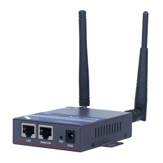
Page 8: Hardware Installation
But the difference doesn’t have any influence to products performance. Panel: Table 2-1 WL-G500 Structure WLINK Tech. WL-G500 series Front Rear There are some different for Antenna interface and indicator light for the expandable Wi-Fi, GPS series. -
Page 9: Led Status
Green Solid light WLAN port enable, but no data sending. Green WLAN Blinking quickly Data is in transmitting Green WLAN port disable Green Solid light Connection ok Green Blinking Data Sending Green Not connection Green Solid light Power supply www.wlink-tech.com... -
Page 10: Dimension
How to Install 2.4.1 SIM/UIM card install If use dual SIM/UIM card router, you may need insert dual SIM before configure it. After installation, please follow below steps to connect the router. Before connecting, please disconnect any power resource of router www.wlink-tech.com... -
Page 11: Serial Port Connection
Before connecting, please disconnect any power resource of router 2.4.4 Power Supply In order to get high reliability, WLINK Series Router adapt supports wide voltage input range: +5V~+36VDC, support hot plug and complex application environment. 2.4.5 Review After insert the SIM/UIM card, connect Ethernet cable and necessary antenna, connect power cable. -
Page 12: Router Configuration
Refer to the figure below. Figure 3-2 Network Connection Step 2 Obtain a IP address automatically or set up IP address,192.168.1.xxx(XXX can be any number between 2~254) Step 3 Run an Interneft Explorer and input “http://192.168.1.1”, to enter identify page. www.wlink-tech.com... -
Page 13: Basic Configuration
Different software version have different web configuration interface, below take G500 2.6.0.1 version as example. After visit the WEB interface, you can check the current status of Router, or modify router configuration via web interface, below is the introduction for the common setting. www.wlink-tech.com... - Page 14 Industrial Cellular Gigabit Router User Manual Figure 3-4 Router Status GUI 3.2.1 Cellular Network Configure Step 1 Single Click Basic Network-> Cellular, you can modify relevant parameter according to the application. www.wlink-tech.com...
-
Page 15: Icmp Check
60s. If the IP address is unreachable and ICMP check is timeout at the first time, it will check 2 times every 3 seconds. If the third time is still failed, the router will redial. The ICMP Check IP is a public IP or company server IP address. www.wlink-tech.com... -
Page 16: Lan Setting
【Rx】 Router will check the 3G/LTE cellular receiver traffic. If no receiver traffic within the defined check interval, the router will implement the specified action reconnect or reboot. Step 2 After Setting, please click “save” icon. ----End 3.2.2 LAN Setting Step 1 Single Click “ Basic Network>LAN” to enter below interface www.wlink-tech.com... - Page 17 Dynamic allocation IP service, after enable, it will show the IP address range and options of lease IP Address Range IP address range within LAN Lease The valid time Step 2 After setting, please click “save” to finish, the device will reboot. ----End www.wlink-tech.com...
-
Page 18: Dynamic Dns Setting
Table 3-3 DDNS Setting Instruction parameter Instruction Default is standard DDNS protocol, for customized protocol, please IP address contact WLINK engineer. use default IP 0.0.0.0 as usually. Auto refresh Set the interval of the DDNS client obtains new IP, suggest 5mins or time above Service Select the DDNS service provider that listed. -
Page 19: Wlan Setting
Step 2 Please Click “ Save “ to finish. WLAN Setting It’s mainly for router which support Wi-Fi, you can modify and configure WLAN parameter through Web GUI, below is the common setting 3.3.1 Basic Setting Step 1 Click “WLAN->Basic Setting” to configure relative parameter www.wlink-tech.com... - Page 20 The channel of wireless network, suggest keep the default Channel Width 20MHZ and 40MHZ alternative Security Support various encryption method Step 2 Please click “Save” to finish. ----End 3.3.2 Wireless Filter Setting Step 1 Single click “WLAN > Wireless Filter”. www.wlink-tech.com...
- Page 21 Only allow the listed MAC address to connect to router by wireless following client Block the follow Prevent the listed MAC address to connect to router by wireless Client Step 2 Please click ”save” to finish ----End 3.3.3 Wireless Survey Step 1 Please click “WLAN> Wireless Survey” to check survey. www.wlink-tech.com...
-
Page 22: Advanced Network Setting
Figure 3-7 Wireless Survey Setting GUI ----End Advanced Network Setting 3.4.1 Port Forwarding Step 1 Please click “Advanced Network > Port Forwarding” to enter the GUI, you may modify the router name, Host name and Domain name according to the application requirement. www.wlink-tech.com... - Page 23 Step 2 Please click ”save” to finish ----End 3.4.2 Port Redirecting Step 1 Please click “Advanced Network > Port Redirecting” to enter the GUI, you may modify the router name, Host name and Domain name according to the application requirement. www.wlink-tech.com...
-
Page 24: Dmz Setting
Instruction Destination The destination address inside the LAN. Address Source If no IP address inside, it will allow all IP address to access. Address If define IP address, it will just allow the defined IP address Restriction to access. www.wlink-tech.com... - Page 25 Forwarded Ports are the WAN to LAN ports that are Ports opened if the "trigger" is activated. Note Port triggering opens an incoming port when your computer is using a specified outgoing port for specific traffic. Step 2 Please click ”save” to finish. ----End www.wlink-tech.com...
- Page 26 Ex-storage: Captive portal file is in extended storage such as SD card. Web Host Configure domain name for the captive portal access. For example, Configure as wlink.tech.com, we might directly access to captive portal page in the website as wlink.tech.com Portal Host Reserved.
-
Page 27: Gps Setting
Step 1 Please click “Advanced Network> GPS” to check or modify the relevant parameter. Figure 3-13 GPS Setting GUI Table 3-17 “GPS” Instruction parameter Instruction GPS Mode Enable/Diable GPS Format NMEA and M2M_FMT(WLINK) Server IP/Port GPS server IP and port www.wlink-tech.com... - Page 28 2234.248130 Latitude, Degrees + minutes. gps_NS character N/S Indicator,N=north or S=south. gps_longitude 11356.626179 ddmm.mm Longitude, Degrees + minutes. gps_EW character indicator, E=east W=west. gps_speed numeric Speed over ground, units is km/h. gps_degrees numeric 91.5 Course over ground, unit is www.wlink-tech.com...
- Page 29 Step 1 Please click “Advanced Network> Upnp/NAT-PMP” to check or modify the relevant parameter. Figure 3-14 UPnp/NAT-PMP Setting GUI Step 2 Please click ”save” to finish. 3.4.8 VRRP Setting Step 1 Please click “Advanced Network> Static DHCP” to check or modify the relevant parameter. www.wlink-tech.com...
- Page 30 Step 2 Please click ”save” to finish. ----End 3.4.9 Static DHCP Setting Step 1 Please click “Advanced Network> Static DHCP” to check or modify the relevant parameter. Figure 3-16 Static DHCP Setting GUI Step 2 Please click ”save” to finish. ----End www.wlink-tech.com...
-
Page 31: Vpn Tunnel
Keep alive retry times. After retry times, GRE tunnel will be re-established. Description Step 2 Please click ”save” to finish. ----End 3.5.2 VPN Client Setting Step 1 Please click “VPN Tunnel> VPN Client” to check or modify the relevant parameter. www.wlink-tech.com... - Page 32 As the configuration requested. Create NAT on As the configuration requested. Tunnel MTU is 1450bytes as default MRU is 1450bytes as default Local IP Defined Local IP address for tunnel Address Step 2 Please click ”save” to finish. ----End www.wlink-tech.com...
-
Page 33: Firewall
Support IP address, MAC address and port filter. Filtering Key Word Support key word filter. Filtering URL Filtering Support URL filter. Step 2 Please click ”save” to finish. 3.6.2 Domain Filtering Step 1 Please click “Firewall> Domain Filtering” to check or modify the relevant parameter. www.wlink-tech.com... -
Page 34: System Management
Support Domain filter. Step 2 Please click ”save” to finish. ----End System Management 3.7.1 Identification Setting Step 1 Please click ”Administrator> Identification” to enter the GUI, you may modify the router name, Host name and Domain name according to self-requirement. www.wlink-tech.com... - Page 35 Default is router, can be set maximum 32 character Domain name Default is empty, support maximum up to 32 character, it is the domain of WAN, no need to configure for most application. Step 2 Please click ”save” to finish ----End www.wlink-tech.com...
-
Page 36: Time Setting
Step 1 Please click “Administrator> time” to check or modify the relevant parameter. Figure 3-20 System Configuration GUI If the device is online but time update is fail, please try other NTP Time Server. Step 2 Please click “save to finish. ----End www.wlink-tech.com... - Page 37 In this page, you can configure the basic web parameter, make it more convenient for usage. Please note the “password” is the router system account password. Figure 3-21 Admin Setting GUI Step 2 Please click save iron to finish the setting ----End www.wlink-tech.com...
- Page 38 Step 1 Please click “Administrator>Schedule Reboot” to check and modify relevant parameter. Figure 3-22 Scheduler Reboot Setting GUI Step 2 Please click save iron to finish the setting ----End 3.7.5 Storage Setting Step 1 Please click “Administrator>Storage” to check and modify relevant parameter. www.wlink-tech.com...
- Page 39 Furthermore, also might upload splash with images together. Picture format should be .png and Picture size is less than 100Kbytes and resolution is 800*600. Picture name is 0001_portal.png, 0002_portal.png and 0003_portal.png. Figure 3-23 SNMP Setting GUI Step 2 Please click save iron to finish the setting www.wlink-tech.com...
- Page 40 M2M platform. The connection protocol is UDP. Heartbeat Interval WLINK router send a heartbeat to M2M platform as report interval time. Heartbeat Retry After retry times, router will implement the Fail Action.
- Page 41 Industrial Cellular Gigabit Router User Manual 3.7.7 DI/DO Setting Step 1 Please click “Administrator>DI/DO Setting” to check and modify relevant parameter. Figure 3-25 DI/DO Setting GUI 3.7.7.1 DI Configure www.wlink-tech.com...
- Page 42 The alarm SMS will send to specified phone group. Each phone group include up to 2 phone numbers. SMS Content 70 ASCII Char Max Number 1 SMS receiver phone number. Number 2 SMS receiver phone number. Step 2 Please click ”save” to finish. 3.7.7.2 DO Configure www.wlink-tech.com...
- Page 43 ON, input the Digital Output keep on status time. Input from 0 to 255 seconds. (0=keep on until the next action) Delay Available when enable Pulse in Alarm On Action/Alarm Off Action. The first pulse will be generated after a “Delay”. www.wlink-tech.com...
- Page 44 (70 ASIC II char max). Number 1 SMS receiver phone number. Number 2 SMS receiver phone number. Step 3 Please click ”save” to finish. 3.7.8 Configuration Setting Step 1 Please click “ Administrator> Back up Configuration ” to do the backup setting www.wlink-tech.com...
- Page 45 Industrial Cellular Gigabit Router User Manual Figure 3-26 Backup and Restore Configuration GUI Restore Default would lose all configuration information, please be careful. Step 2 After setting the backup and restore configuration. The system will reboot automatically. ----End www.wlink-tech.com...
-
Page 46: System Log Setting
Step 1 Please click “Administrator> Logging” to start the configuration, you can set the file path to save the log (Local or remote sever). Figure 3-27 System log Setting GUI Step 2 After configure, please click “Save” to finish. ----End www.wlink-tech.com... -
Page 47: Firmware Upgrade
Step 1 Please click “Administrator>firmware upgrade” to open upgrade firmware tab. Figure 3-28 Firmware Upgrade GUI When upgrading, please don’t cut off the power. 3.7.11 System Reboot Step 1 Please click “Administrator>Reboot” to restart the router. System will popup dialog to remind “Yes” or “NO” before the next step. www.wlink-tech.com... -
Page 48: Debugging Setting
Step 1 Please click “Debugging>Logs” to check and modify relevant parameter. Figure 3-29 Logs GUI Step 2 After configure, please click “Save” to finish. ----End 3.8.2 Ping Setting Step 1 Please click “Debugging>Logs” to check and modify relevant parameter. www.wlink-tech.com... - Page 49 Figure 3-30 Ping GUI Step 2 After configure, please click “Save” to finish. ----End 3.8.3 Trace Setting Step 1 Please click “Debugging>Trace” to check and modify relevant parameter. Figure 3-31 Trace GUI Step 2 After configure, please click “Save” to finish. ----End www.wlink-tech.com...
-
Page 50: Rst" Button For Restore Factory Setting
The system will be restored to factory. Table 3-25 System Default Instruction Parameter Default setting LAN IP 192.168.1.1 LAN Subnet Mask 255.255.255.0 DHCP server Enable User Name admin Password admin After reboot, the previous configuration would be deleted and restore to factory settings. www.wlink-tech.com... -
Page 51: Configuration Instance
1)Upload Portal file and Splash.html by local Upload portal images and splash.html in router for the Slider (0001_portal.png, 0002_portal.png, and 0003_portal.png) to the Router under the “ Administration / Storage Settings” menu. Furthermore, also might upload splash with images together. www.wlink-tech.com... - Page 52 Each Ad file just supports 3 Ad portal images. Picture format is acceptable for png/jpg and image size is less than 100Kbytes and resolution is 800*600. Picture name is 0001_portal.png, 0002_portal.png and 0003_portal.png. Furthermore, please keep image names the same between portal file and splash.html. www.wlink-tech.com...
- Page 53 Industrial Cellular Gigabit Router User Manual Finally, we can see the results by connect to router WIFI 2)Modify portal file storage path www.wlink-tech.com...
-
Page 54: Gps Settings
4.2 GPS Settings The feature is requested hardware supports GPS feature. Step 1 Please click “Advanced Network> GPS” to view or modify the relevant parameter. Table 4-2 “GPS” Instruction parameter Instruction GPS Mode Enable/Disable GPS Format NMEA and M2M_FMT(WLINK) www.wlink-tech.com... - Page 55 Router ID, gps_date, gps_time, gps_use, gps_latitude, gps_NS, gps_longitude, gps_EW, gps_speed, gps_degrees, gps_FS, gps_HDOP, gps_MSL 2. Example 0001_R081850ac,150904,043215.0,06,2234.248130,N,11356.626179,E,0.0,91.5,1,1.2,9 3. GPS data description Field Name Format Example Description Router ID String 0001_R081850 0001 customizable product router indicator. 081850ac Last 8digits of routers MAC address. www.wlink-tech.com...
- Page 56 W=west. gps_speed numeric Speed over ground, units is km/h. gps_degrees 91.5 numeric Course over ground, unit is degree. gps_FS digit Position Fix Status Indicator, gps_HDOP numeric HDOP, Horizontal Dilution of Precision gps_MSL 97.5 numeric MSL Altitude, units is meter. www.wlink-tech.com...
Need help?
Do you have a question about the WL-G500 Series and is the answer not in the manual?
Questions and answers