Table of Contents
Advertisement
Advertisement
Table of Contents

Related Manuals for Extech Instruments MM750W


Summary of Contents for Extech Instruments MM750W
- Page 1 USER MANUAL Wireless Datalogging CAT IV True RMS Multimeter Model MM750W...
-
Page 2: Table Of Contents
WIRELESS COMMUNICATIONS OVERVIEW....................17 INSTALLING A WIRELESS MODULE ......................17 OBTAINING THE APPLICATION (APP) ....................... 17 USING THE APPLICATION ........................17 FCC COMPLIANCE ..........................18 Maintenance ....................18 BATTERY INSTALLATION ......................... 19 FUSE REPLACEMENT ..........................19 Specifications ....................20 MM750W-en-GB_v1.1 12/18... -
Page 3: Introduction
Introduction Thank you for selecting the Extech Model MM750W Wireless Datalogging CAT IV True RMS Multimeter. Proper use and care of this meter will provide many years of reliable service. Please visit our website (www.extech.com) to check for the latest version of this User Manual and Customer Support. - Page 4 If this device is going to be unused for an extended period, remove the batteries. • Expired or damaged batteries can cause cauterization on contact with the skin. Always use suitable hand protection. • Do not short-circuit the batteries and do not dispose of batteries in fire. MM750W-en-GB_v1.1 12/18...
- Page 5 9. Do not use the meter immediately before, during, or after an electrical storm (thunder, lightning, etc.). 10. If the equipment is used in a manner not specified by the manufacturer, the protection provided by the equipment may be impaired. MM750W-en-GB_v1.1 12/18...
-
Page 6: Meter Description
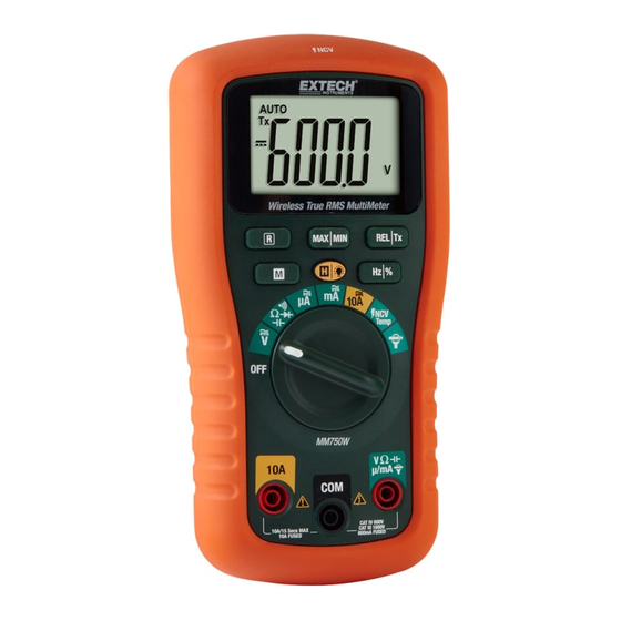
5. Positive 10A input terminal 6. COM negative input terminal 7. Positive terminal for all inputs except 10A METER BACK 1. Wireless module compartment 2. Test lead holders 3. Battery compartment 4. 600mA/1000V Fuse compartment 5. Tilt stand 6. 10A/1000V Fuse compartment MM750W-en-GB_v1.1 12/18... -
Page 7: Control Buttons
Automatic range Diode test Continuity test Data hold Relative zero Maximum-Minimum mode Temperature units Non-contact voltage detector Units of measure 10. Measurement display digits 11. Low battery icon 12. Minus sign 13. AC and DC symbols 14. Wireless Transmission MM750W-en-GB_v1.1 12/18... -
Page 8: Multimeter Operating Instructions
2. Press the REL button to store the reading; the relative icon will appear. 3. The display will then indicate the difference between the stored value and subsequent measurements. 4. Press the REL button to exit the relative mode. MM750W-en-GB_v1.1 12/18... -
Page 9: Lcd Backlight
Note that the APO will be re-enabled on the next cycle of power to the meter. LOW BATTERY INDICATION The battery icon will appear when the battery voltage is critical. Replace the battery before continuing to use the meter. MM750W-en-GB_v1.1 12/18... -
Page 10: Dc Voltage Measurements
5. Press the HZ/% button to indicate ‘Hz’ and read the frequency in the display. 6. Press the Hz/% button again to indicate ‘%’. Read the duty cycle % in the display. 7. Press Hz/% again to exit. MM750W-en-GB_v1.1 12/18... -
Page 11: Dc Current Measurements
7. Touch the black test probe tip to the negative side of the circuit. Touch the red test probe tip to the positive side of the circuit. 8. Apply power to the circuit and read the current on the display. MM750W-en-GB_v1.1 12/18... -
Page 12: Ac Current, Frequency, Duty Cycle Measurements
9. Press the Hz/% button to indicate ‘Hz’. Read the frequency on the display. 10. Press the Hz/% button again to indicate ‘%’. Read the duty cycle on the display. 11. Press the Hz/% button to return to current measurement. MM750W-en-GB_v1.1 12/18... -
Page 13: Clamp Adaptor Measurements Ac/Dc
7. For AC, Press the Hz/% button to indicate ‘Hz’. Read the frequency on the display. 8. For AC, Press the Hz/% button again to indicate ‘%’. Read the duty cycle on the display. 9. Press the Hz/% button to return to current measurement. MM750W-en-GB_v1.1 12/18... -
Page 14: Resistance Measurements
5. Touch the test probe tips to the circuit or wire under test. 6. If the resistance is less than approximately 50 ohms, an audible tone will sound. If the circuit is open, the display will indicate ‘OL’. MM750W-en-GB_v1.1 12/18... -
Page 15: Diode Test
4. Short press the REL button to null any stray signal. 5. Touch the test probe tips across the circuit or part under test. 6. Read the capacitance on the display. Note that larger capacitors can take some time before stabilizing. MM750W-en-GB_v1.1 12/18... -
Page 16: Temperature Measurements
The number of dashes is proportional to the strength of the voltage source as is the periods between audible beeps. Note that the meter flashes red with each audible beep. MM750W-en-GB_v1.1 12/18... -
Page 17: Wireless Communication
Wireless Communication WIRELESS COMMUNICATIONS OVERVIEW We ship the MM750W with a Bluetooth® Wireless Datalogging Module (DAT12) installed in the compartment on the back (top) of the meter. The DAT12 transmits real- time readings and logged readings to paired iOS® or Android™ devices using the free ExView®... -
Page 18: Fcc Compliance
2. This device must accept any interference received, including interference that may cause undesired operation. IC: 1590A-MM750W FCC ID: IWK-MM750W This equipment has been tested and found to comply with the limits for a Class B digital device, pursuant to part 15 of the FCC Rules. -
Page 19: Battery Installation
600mA/1000V fuse compartment is located on the left (see Meter Description section of this manual). 4. Insert the fuse into the fuse holder. 5. Close the fuse compartment and secure with the screws. MM750W-en-GB_v1.1 12/18... -
Page 20: Specifications
(0.8% reading + 6 digits) Continuity 600.0 0.1 Audible beeper < 50 threshold (5.0% reading + 7 digits) Capacitance 9.999nF 0.001nF (5.0% reading + 5 digits) 9.999uF 0.001uF 99.99uF 0.01uF (10.0% reading + 10 digits) 9.999mF 0.001mF 99.99mF 0.01mF MM750W-en-GB_v1.1 12/18... - Page 21 Storage Temperature -20C to 60C (-4F to 140F) Operating Humidity Max 80% up to 31C (87F) decreasing linearly to 50% at 40C (104F) Storage Humidity <80% Operating Altitude 2000m (7000 ft.) maximum. Weight 415g (14.6 oz.) without battery MM750W-en-GB_v1.1 12/18...
- Page 22 Customer Support Telephone: U.S. (866) 477-3687; International +1 (603) 324-7800 Calibration, Repair, and Returns email: repair@extech.com Technical Support: https://support.flir.com Copyright © 2018 FLIR Systems, Inc. All rights reserved including the right of reproduction in whole or in part in any form ISO-9001 Certified www.extech.com MM750W-en-GB_v1.1 12/18...
Need help?
Do you have a question about the MM750W and is the answer not in the manual?
Questions and answers