
Subscribe to Our Youtube Channel
Related Manuals for Extech Instruments MiniTec MN36


Summary of Contents for Extech Instruments MiniTec MN36
- Page 1 USER MANUAL MiniTec Series Manual Ranging Mini MultiMeter Model MN35 800.561.8187 information@itm.com www. .com...
-
Page 2: International Safety Symbols
Introduction Congratulations on your purchase of Extech’s MN35 Manual Ranging Multimeter. This meter measures AC/DC Voltage, DC Current, Resistance, Temperature, Battery Test, Diode Test and Continuity. This meter is shipped fully tested and calibrated and, with proper use, will provide years of reliable service. Please visit our website (www.extech.com) to check for the latest version of this User Guide, Product Updates, and Customer Support. Safety International Safety Symbols This symbol, adjacent to another symbol or terminal, indicates the user must refer to the manual for further information. This symbol, adjacent to a terminal, indicates that, under normal use, hazardous voltages may be present Double insulation Safety Precautions 1. Improper use of this meter can cause damage, shock, injury or death. Read and understand this user manual before operating the meter. 2. Make sure any covers or battery doors are properly closed and ured. 3. Always remove the test leads before replacing the battery or fuses. 4. Inspect the condition of the test leads and the meter itself for any damage before operating the meter. Repair any damage before use. 5. Do not exceed the maximum rated input limits. 6. Use great care when making measurements if the voltages are greater than 25VAC rms or 35VDC. These voltages are considered a shock hazard. 7. Always discharge capacitors and remove power from the device under test before performing Diode, Resistance or Continuity tests. 8. Remove the battery from the meter if the meter is to be stored for long periods. 9. -
Page 3: Meter Description
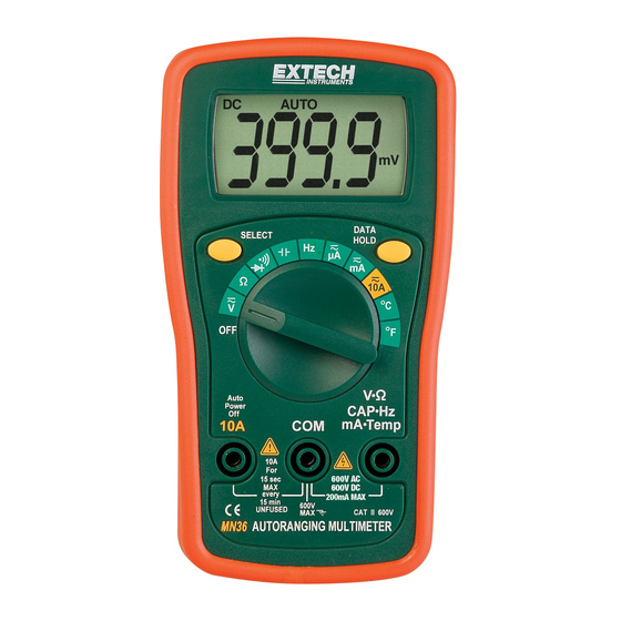
Meter Description 1. LCD Display 2. Hold button 3. Function switch 4. COM jack 5. 10A jack 6. Positive jack Note: Tilt stand and battery access is on the rear of unit. Operating Instructions Note: If “H” and a blank screen appear when the meter is turned on the HOLD feature is active. Press the HOLD button to exit the HOLD mode. AC or DC Voltage Measurements 1. Insert the black test lead banana plug into the negative COM jack and the red test lead banana plug into the positive V jack. 2. Turn the rotary switch to the highest VAC or VDC position. 3. Touch the test probes to the circuit under test and read the voltage on the display. 4. Reset the function switch to successively lower positions to obtain a higher resolution reading. If the polarity is reversed (DC voltage only), the display will show (‐) minus before the value. DC Current Measurements CAUTION: Do not make current measurements on the 10A scale for longer than 15 seconds followed by a 15 minute cool down period. Exceeding 15 seconds may cause damage to the meter and/or the test leads. 1. Insert the black test lead banana plug into the negative COM jack. 2. For current measurements up to 200mA DC, set the function switch to the 200mA DC position and insert the red test lead banana plug into the V//mA jack. 3. For current measurements up to 10A DC, set the function switch to the 10A DC range and insert the red test lead banana plug into the 10A jack. ... -
Page 4: Resistance Measurements
Resistance Measurements 1. Insert the black test lead banana plug into the negative COM jack and the red test lead banana plug into the positive V//mA jack. 2. Set the function switch to the highest position. 3. Touch the test probe tips across the circuit or part under test. It is best to disconnect one side of the part under test so the rest of the circuit will not interfere with the resistance reading. 4. Read the resistance in the display and then set the function switch to the lowest position that is greater than the actual or any anticipated resistance. Temperature Measurements WARNING: To avoid electric shock, disconnect test leads from any source of voltage before making a temperature measurement. Be sure that the thermocouple has been removed before changing to any other measurement function. 1. Insert the type K thermocouple probe into the V//mA and COM jacks. 2. Turn the rotary switch to the F or C position. 3. Read the temperature on the display. Continuity Measurements 1. Insert the black test lead banana plug into the negative COM jack and the red test lead banana plug into the positive V//mA jack. Observe polarity. 2. Turn the rotary switch to the •))) position. 3. Touch the test probes to the circuit or device under test. If the resistance is less than approximately 40 the buzzer will sound. Diode Measurements 1. Insert the black test lead banana plug into the negative COM jack and the red test lead banana plug into the positive V//mA jack. 2. -
Page 5: Maintenance
Maintenance WARNING: To avoid electric shock, disconnect the test leads from any source of voltage before removing the battery/fuse cover. WARNING: To avoid electric shock, do not operate your meter until the battery/fuse cover is in place and fastened securely. This Multimeter is designed to provide years of dependable service, if the following care instructions are performed. Keep the meter dry. Use and store the meter in mild ambient conditions. Temperature extremes can shorten the life of the electronic parts and distort or melt plastic parts. Handle the meter gently. Dropping it can damage the electronic parts or the case. Keep the meter clean. Wipe the case occasionally with a damp cloth. DO NOT use chemicals, cleaning solvents or detergents. Use only fresh batteries of the recommended size and type. Remove old or weak batteries so they do not leak and damage the unit. If the meter is to be stored for a long period of time, the batteries should be removed to prevent damage to the unit. MN35-EU-EN V2.3 4/13 800.561.8187 information@itm.com www. .com... -
Page 6: Battery Replacement
Battery Replacement WARNING: To avoid electric shock, disconnect the test leads from any source of voltage before removing the battery/fuse cover. 1. Disconnect the test leads from the meter. 2. Remove the rubber holster (if in place). 3. Remove the two screws securing the rear cover using a Phillips head screwdriver. 4. Lift the cover off and replace the battery observing the correct polarity. 5. Insert the new battery into the battery holder. 6. Replace the rear cover and secure with the screws. Never dispose of used batteries or rechargeable batteries in household waste. As consumers, users are legally required to take used batteries to appropriate collection sites, the retail store where the batteries were purchased, or wherever batteries are sold. Disposal: Do not dispose of this instrument in household waste. The user is obligated to take end‐of‐life devices to a designated collection point for the disposal of electrical and electronic equipment. Other Battery Safety Reminders o Never dispose of batteries in a fire. Batteries may explode or leak. o Never mix battery types. Always install new batteries of the same type. Fuse Replacement WARNING: To avoid electric shock, disconnect the test leads from any source of voltage before removing battery/fuse cover. Disconnect the test leads from any circuit being measured. Remove the rubber holster (if in place). Remove the two screws securing the rear cover using a Phillips head screwdriver. Remove the rear cover. Remove the old fuse by gently pulling up on it. Install the new fuse by gently pushing it into the holder. Always use a fuse of the proper size and value; 250mA/250V fast blow. Replace the rear cover and secure with the screws. ... -
Page 7: Specifications
Specifications Function Range Accuracy DC Voltage (V DC) 200.0mV 2.000V (0.5% reading + 2 digits) 20.00V 200.0V (0.8% reading + 2 digits) 600V AC Voltage (V AC) 200.0V (1.2% reading + 10 digits) (40 ‐ 400Hz) 600V (1.5% reading + 2 digits) DC Current (A DC) 200.0mA (3.0% reading + 5 digits) 10.00A (0.8% reading + 4 digits) Resistance 200.0 2.000k (0.8% reading + 2 digits) 20.00k 200.0k (3.0% reading + 3 digits) 20.00M Temp F ‐4 to 1400F ‐4 to 59°F; (2.5% reading + 19 digits) 60 to 750°F (1.0% reading + 9 digits) 751; to 1400°F; (2.5% reading + 19 digits) ... - Page 8 Relative Humidity M aximum relative humidity 80% for temperatures up to 31°C decreasing linearly to 50% relative humidity at 40°C. Operating Altitude 2000 meters (7000ft) maximum. Weight 153g (5.4 oz.) Size 138mm x 72mm x 38mm (5.43” x 2.83” x 1.5”) Safety For indoor use and in accordance with Overvoltage Category II, Pollution Degree 2. Category II includes local level, appliance, portable equipment, etc., with transient overvoltages less than Overvoltage Category III. Symbols AC (voltage) DC (direct current or voltage) •))) Continuity and Diode test mV, V millivolt, volt (voltage) k M ohm, kilohm, megohm (resistance) µA, mA, A microamp, milliamp, Amp (current) º º F, C Degrees Fahrenheit, centigrade (temperature) º Low battery HOLD Display hold ...
Need help?
Do you have a question about the MiniTec MN36 and is the answer not in the manual?
Questions and answers