
Subscribe to Our Youtube Channel
Related Manuals for Extech Instruments MultiMaster MM560


Summary of Contents for Extech Instruments MultiMaster MM560
- Page 1 User’s Guide MultiMaster™ Digital MultiMeter Series With PC Interface Models: MM560 MM570...
- Page 2 The warranty set forth above is inclusive and no other warranty, whether written or oral, is expressed or implied. Copyright © 2002 Extech Instruments Corporation. All rights reserved including the right of reproduction in whole or in part in any form.
- Page 3 Introduction Congratulations on your purchase of Extech model MM560 or MM570 digital multimeter. Properly used, this meter will provide many years of reliable service. MultiMaster™ Meters provides high resolution, high accuracy, true rms measurements of AC Voltage and Current, DC Voltage and Current, AC+DC, Resistance, Frequency, Capacitance, Duty Cycle, dBm, Peak, %4-20, Diode, and Continuity.
- Page 4 7. Use great care when making measurements if the voltages are greater than 25VAC rms or 35VDC. These voltages are considered a shock hazard. 8. Always discharge capacitors and remove power from the device under test before performing Capacitance, Diode, Resistance or Continuity tests.
-
Page 5: Specifications
Specifications DC VOLTAGE Accuracy Range MM570 MM560 500.00 mV, 0.02% + 2d 0.03% + 2d 5.0000V, 50.000V 500.00V 0.04% + 2d 0.05% + 2d 1000.0V 0.05% + 2d 0.1% + 2d NMRR: >60dB @ 50/60Hz, CMRR: >120dB @ DC, 50/60Hz, Rs=1kΩ Input impedance: 10MΩ, 30pF nominal (80pF nominal for 500mV range) DC CURRENT Range... - Page 6 AC & AC+DC VOLTAGE Accuracy* MM570 MM560 Range 20Hz to 45Hz 500.00mV, 1.5% + 40d unspecified 5.0000V, 50.000V 500.00V, 1000.0V unspecified 45Hz to 300Hz 500.00mV 0.3% + 20d 0.8% + 60d 5.0000V, 50.000V 0.8% + 20d 500.00V, 1000.0V 0.4% + 40d 300Hz to 5kHz 300Hz to 1kHz 500.00mV...
- Page 7 AC & AC+DC CURRENT Accuracy MM570 MM560 Range Burden Voltage 50Hz to 60Hz 0.5% + 50d 1.0% + 40d 500.00µA, 0.15mV/µA 5000.0µA 50.000mA, 3.3mV/mA 500.00mA 5.0000A, 0.03V/A 10.000A* 40Hz to 1kHz 0.7% + 50d 1.0% + 40d 500.00µA, 0.15mV/µA 5000.0µA 50.000mA, 3.3mV/mA 500.00mA...
-
Page 8: Duty Cycle
CAPACITANCE Range Accuracy* 50.00nF, 500.0nF 0.8% + 3d 1.0% + 3d 5.000µF 2.0% + 3d 50.00µF 3.5% + 5d 500.0µF 5.0% + 5d 9999µF *Accuracies with film capacitor or better FREQUENCY, AC LINE LEVEL Range 5.0000Hz to 200.000kHz Accuracy 0.002% + 4d Sensitivity 500mV range 0.1V min... - Page 9 DC Loop Current %4 to 20mA: 4mA = 0% (zero), 20mA = 100% (span), Resolution: 0.01%, Accuracy: ±25d Diode Test: Accuracy: 1%+1d, Current 0.8mA(typical), Open circuit: <3.5VDC Peak Capture (Instantaneous Peak Hold): Accuracy: Specified accuracy ±100 digits for changes > 0.8ms in duration Audible Continuity: Measurement threshold: Between 20Ω...
- Page 10 Auto Power Off: After 17 minutes of inactivity with no input signal. Power consumption during auto power off; 20µA Safety: The MultiMaster™ Series meters are intended for indoor use and are protected, against the users, by double insulation per EN61010-1 and IEC61010-1 2nd Edition (2001) to CAT III 1000V &...
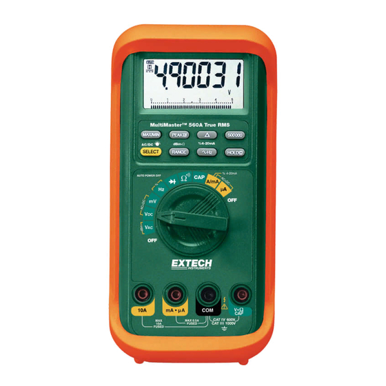
- Page 11 Meter Description (MM570 Shown) 1. Liquid Crystal display 2. Function push-keys 3. Rotary function switch 4. 10A/-T2 input jack 5. V/Hz/Ω/Cap/+T1 input jack 6. COM input jack/-T1 input 7. mA-uA current/+T2 input jack NOTE: RS-232 Optical interface is located on the top rear of the meter. Considerations &...
- Page 12 DC+AC True RMS DC+AC True RMS calculates both of the AC and DC components given by the expression when making measurement, and can responds accurately to the total effective RMS value regardless of the waveform. Distorted waveforms with the presence of DC components and harmonics may cause: 1) Overheated transformers, generators and motors to burn out faster than normal...
- Page 13 Analog bar-graph The analog bar graph provides a visual indication of measurement like a traditional analog meter needle. It is excellent in detecting faulty contacts, identifying potentiometer clicks, and indicating signal spikes during adjustments. Default Functions The Multimaster™ will set the function last used as the default function. For example, if dBm is last used in the VAC position, the meter will display dBm the next time that function is selected.
-
Page 14: Operation
Operation Measurement Considerations NOTICE: Read and understand all warning and caution statements listed in the safety section of this operation manual prior to using this meter. 1. Always move the rotary function switch to the OFF position when the meter is not in use. This meter has Auto Power OFF that automatically shuts the meter OFF if 17 minutes elapse without activity. - Page 15 2. For current measurements up to 5000µA, set the function switch to the "µA" position and insert the red test lead into the mA-µA jack. 3. For current measurements up to 500mA, set the function switch to the "A/mA" position and insert the red test lead into the mA-µA jack. 4.
- Page 16 6. For Continuity tests, if the resistance is less than the threshold (20Ω to 200Ω), an audible tone will sound.
- Page 17 Capacitance Measurements 1. Insert the black lead into the negative COM jack and the red test lead into the positive CAP jack. 2. Set the function switch to the " CAP" position. 3. Press the SELECT key momentarily to select Capacitance 4.
- Page 18 Diode Test 1. Insert the black lead into the negative COM jack and the red test lead into the positive CAP jack 2. Set the function switch to the " CAP" position. 3. Press the SELECT key momentarily to select the diode function 4.
- Page 19 Relative mode Relative Zero allows the user to offset the meter by using the displayed value as the zero reference value. Practically all of the displayed readings can be set as the relative reference value including the MAX/MIN recording feature. Press the key momentarily to activate and to exit Relative Zero mode.
- Page 20 RS-232 PC Interface This instrument is equipped with an optically isolated interface port (located on the rear of the meter). An optional Windows software and interface package is available for data acquisition applications. This optional kit is required to connect the meter to a PC. The software provides digital, analog, and graphical data displays.
-
Page 21: Repair And Calibration Services
Fuse Replacement 1. Remove the four screws from the case bottom and stand using a Philips head screwdriver. 2. Lift the end of the case bottom nearest the input jacks until it unsnaps from the case top 3. Replace the battery or blown fuse(s) 4.
Need help?
Do you have a question about the MultiMaster MM560 and is the answer not in the manual?
Questions and answers