
Subscribe to Our Youtube Channel
Related Manuals for Extech Instruments MultiTec MT310


Summary of Contents for Extech Instruments MultiTec MT310
- Page 1 User’s Guide MultiTec Series Digital MultiMeters with PC Interface Models: MT310 MT320 MT330...
-
Page 2: Warranty
WARRANTY EXTECH INSTRUMENTS CORPORATION warrants this instrument to be free of defects in parts and workmanship for three years from date of shipment (a six month limited warranty applies on sensors and cables). If it should become necessary to return the instrument for service during or beyond the warranty period, contact the Customer Service Department at (781) 890-7440 ext. - Page 3 Introduction Congratulations on your purchase of Extech model MT310, MT320, or MT330 digital multimeter. Properly used, this meter will provide many years of reliable service. All models measures AC/DC Voltage/Current, Resistance, Frequency and Capacitance. All models are Autoranging and include a PC Interface feature. The MT320 and MT330 also measure temperature.
- Page 4 Safety Precautions Improper use of this meter can cause damage, shock, injury or death. Read and understand this user manual before operating the meter. Make sure any covers or battery doors are properly closed and secured. Always remove the test leads before replacing the battery or fuses. Inspect the condition of the test leads and the meter itself for any damage before operating the meter.
-
Page 5: Specifications
400.0mV ±(0.3% reading + 5 digits) (V DC) 4.000V, 40.00V, 400.0V, ±(0.1% reading + 5 digits)MT330 ±(0.3% reading + 5 digits)MT320 ±(0.5% reading + 5 digits)MT310 1000V ±(0.5% reading + 5 digits) ±(1.5% reading + 5 digits) AC Voltage 100.0-400.0mV (V AC) 4.000V,40.00V, 400.0V... - Page 6 Function Ranges Accuracy Resistance ±(0.5% reading + 10 digits) 400.0Ω, 4.000kΩ, 40.00kΩ, 400.0kΩ, 4000kΩ ±(1% reading + 5 digits) 40.00MΩ Frequency 500.0mHz Not specified 5.000Hz, 50.00Hz, 500.0Hz, 5.000kHz, 50.00kHz, ±(0.1% reading + 2 digits) 500.0kHz, 5.000MHz, 10.00MHz (250mVac peak minimum) Capacitance 40.00nF, 400.0nF, 4.000uF, 40.00uF, 100.0uF ±...
- Page 7 Input Limit Specifications Function Maximum Input V DC or V AC 1000V DC or AC Peak, < 10 seconds mA DC/AC 400mA DC/AC, fused 250V, 0.5A A DC/AC 20A DC/AC, < 30 seconds (every 15min); Fused 250V, 20A Frequency 250V DC or AC peak Resistance 250V DC or AC peak, <10 seconds Duty Cycle...
- Page 8 µA, mA ranges: 500mA/250V ceramic; 20A range: 20A/250V ceramic Fuses Operating Temperature F to 104 F (0 C to 40 Storage Temperature F to 140 F (-20 C to 60 Accuracy Temperature F to 82 F (18 C to 28 Relative Humidity <...
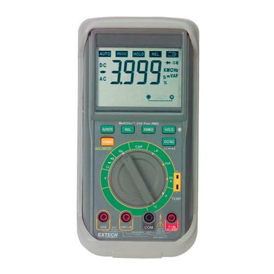
- Page 9 Display AutoRange mode DC current or voltage Negative (minus) sign AC current or voltage Input jack status icons 20A blown fuse indicator uA/mA blown fuse indicator Incorrect test lead insertion indicator (active in Capacitance, Hz, Ohms, Diode, Continuity and ACV/DCV modes) Power warning for Ohm, Cap and Diode 10.
-
Page 10: Operation
Operation Measurement Preparations and Considerations ALWAYS push the power key to the OFF position when the meter is not in use. This meter has Auto Power OFF that automatically shuts the meter OFF if 30 minutes elapse without activity. To recover from Auto OFF, press any key. - Page 11 AC or DC Current Measurements CAUTION: Do not make current measurements on the 20A scale for longer than 30 seconds. Exceeding 30 seconds may cause damage to the meter and/or the test leads. Insert the black test lead into the negative COM jack. For current measurements up to 4000µA, set the function switch to the "µA"...
- Page 12 Resistance and Continuity Measurements Set the function switch to the "OHM" position. Insert the black test lead banana plug into the negative COM jack and the red test lead banana plug into the positive jack. For Continuity, press the "DC/AC" key until the " "...
- Page 13 Diode Test Set the function switch to " " position. Press the "DC/AC" key until the " …" symbol appears on the display. Insert the black lead into the negative COM jack and the red test lead into the positive jack Touch the test probe tips to the diode or semiconductor junction you wish to test.
- Page 14 Temperature Measurements (MT320 and MT330 only) WARNING: To avoid electric shock, disconnect test leads from any source of voltage before making a temperature measurement. Be sure that the thermocouple has been removed before changing to any other measurement function. Set the function switch to the " F or C"...
- Page 15 Relative Mode The relative measurement feature allows the user to make measurements relative to a stored reference value. A reference value can be stored and measurements can be made in comparison to that value. The displayed value is the difference between the reference value and the measured value. Perform any measurement as described in the operating instructions.
-
Page 16: Maintenance
Maintenance WARNING: To avoid electrical shock, disconnect the test leads from any source of voltage before removing the back cover or the battery/fuse door. Do not operate your meter until the battery/fuse door are in place and fastened securely. Cleaning the Meter: Wipe the case occasionally with a damp cloth. DO NOT use chemicals, cleaning solvents, abrasives or detergents. - Page 17 Replacing the Fuses Open the battery/fuse door by loosening the two screws on the battery/fuse door using a Phillips head screwdriver. Remove the old fuse from its holder by gently pulling it out. To access the 20A fuse, remove the third screw under the tilt stand, remove the back cover and gently lift the printed circuit boards.
- Page 18 PC Interface Installation Start Windows 95/98. Insert the program disk into the floppy drive (drive A: for example) Select "START" and then "RUN" from the Windows menu. Type "A:\SETUP.EXE" in the "OPEN" box and select "OK" Follow the installation instructions on the screen. Operation Connect the RS-232 cable between the meter’s DB-9 connector (top of meter) and the PC’s serial port.
Need help?
Do you have a question about the MultiTec MT310 and is the answer not in the manual?
Questions and answers