
Related Manuals for HT Instruments HT4020


Summary of Contents for HT Instruments HT4020
- Page 1 ENGLISH User manual 1.800.561.8187 information@itm.com www. .com Copyright HT ITALIA 2013 Release EN 2.00 - 04/02/2013...
-
Page 2: Table Of Contents
HT4020 - HT4022 Table of Contents: SAFETY PRECAUTIONS AND PROCEDURES ............. 2 1.1. Preliminary instructions ..................... 2 1.2. During use ......................... 3 1.3. After use ..........................3 1.4. Definition of measuring (overvoltage) category ..............3 GENERAL DESCRIPTION ....................4 ... -
Page 3: Safety Precautions And Procedures
HT4020 - HT4022 1. SAFETY PRECAUTIONS AND PROCEDURES This instrument has been designed in compliance with IE/EN61010-1 directive. For your own safety and to avoid damaging the instrument we suggest you follow the procedures hereby prescribed and to read carefully all the notes preceded by the symbol... -
Page 4: During Use
HT4020 - HT4022 1.2. DURING USE CAUTION Non compliance with CAUTIONs and/or instructions may cause damage to the tester or its components or injure the operator. Remove the clamp jaw from the conductor or circuit under test before changing the range. -
Page 5: General Description
HT4020 - HT4022 2. GENERAL DESCRIPTION Those instruments HT4020 and HT4022 can perform the herewith measurements: AC TRMS voltage DC voltage AC TRMS current Harmonic AC voltage (from DC to 25 components) and THD% (HT4022) Harmonic AC current (from 1... -
Page 6: Operating Instructions
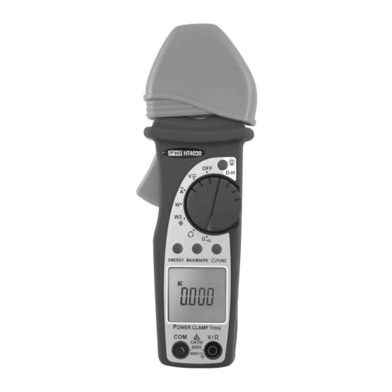
CAPTION: 1. Inductive clamp jaw 2. Safety guard 3. D-H, 4. Jaw trigger 5. Rotary selector switch. 6. ENERGY key (HT4020) ENERGY/H key (HT4022) FUNC key (HT4020) FUNC / HARM key (HT4022) 8. MAX/MIN/PK key (HT4020) MAX/MIN/PK/H key (HT4022) 9. LCD display 10. -
Page 7: Rubber Cap Use To Hold Test Leads
HT4020 - HT4022 4.1.3. Rubber cap use to hold test leads A rubber holster is provided with the instrument. This standard accessory, when fitted on the top of the clamp, can hold one of the two test leads, as shown in Fig. 3. -
Page 8: Description Of Function Keys
HT4020 - HT4022 4.2. DESCRIPTION OF FUNCTION KEYS 4.2.1. D-H/ This key enables the HOLD function. The symbol "H" is displayed when this function is enabled. To disable this function press the D-H key again or rotate the selector switch to another position. -
Page 9: Operating Instructions
HT4020 - HT4022 4.3. OPERATING INSTRUCTIONS 4.3.1. AC/DC Voltage measurement CAUTION The maximum voltage input is 600V. Do not attempt to take any voltage measurements exceeding the limits indicated in this manual. Exceeding the limits could cause electrical shock or damage to the instrument. -
Page 10: Ac Voltage Frequency Measurement
HT4020 - HT4022 4.3.2. AC Voltage frequency measurement CAUTION The maximum voltage input is 600V. Do not attempt to take any voltage measurements exceeding the limits indicated in this manual. Exceeding the limits could cause electrical shock or damage to the instrument. -
Page 11: Measurement Of Voltage Harmonics (Ht4022)
HT4020 - HT4022 4.3.3. Measurement of Voltage Harmonics (HT4022) CAUTION The maximum Voltage input is 600V. Do not attempt to take any voltage measurements exceeding the limits indicated in this manual. Exceeding the limits could cause electrical shock or damage to the instrument. -
Page 12: Resistance And Continuity Test
HT4020 - HT4022 4.3.4. Resistance and continuity test CAUTION Before attempting any resistance measurement remove the power from the circuit under test and discharge all the capacitors, if present. Fig. 7: Use of instrument for resistance and continuity test ... -
Page 13: Ac Current Measurement
HT4020 - HT4022 4.3.5. AC Current measurement CAUTION Before attempting any measurement disconnect all the test leads from the circuit under test and from the meter's input terminals. Fig. 8: Use of instrument for AC current measurements 1. Select the “ ” position 2. -
Page 14: Ac Frequency Current Measurement
HT4020 - HT4022 4.3.6. AC Frequency current measurement CAUTION Before attempting any measurement disconnect all the test leads from the circuit under test and from the meter's input terminals. Fig. 9: Use of instrument for AC current frequency measurement 1. Select the “ ” position 2. -
Page 15: Measurement Of Current Harmonics (Ht4022)
HT4020 - HT4022 4.3.7. Measurement of Current Harmonics (HT4022) CAUTION Before attempting any measurement disconnect all the test leads from the circuit under test and from the meter's input terminals. Fig. 10: Use of instrument for AC harmonic current measurement 1. -
Page 16: Power/Energy Measurement On Single Phase System
HT4020 - HT4022 4.3.8. Power/Energy measurement on single phase system CAUTION The maximum Voltage input is 600V. Do not attempt to take any voltage measurements exceeding the limits indicated in this manual. Exceeding the limits could cause electrical shock or damage to the instrument. -
Page 17: Power/Energy Measurement On Three Phase Balanced System
HT4020 - HT4022 4.3.9. Power/Energy measurement on three phase balanced system CAUTION The maximum input for Voltage measurements is 600V. Do not attempt to take any voltage measurement exceeding the limits indicated in this manual. Exceeding the limits could cause electrical shock at the operator and damages to the clamp meter. -
Page 18: Detection Of Phase Sequence Indication With 1 Wire Method
HT4020 - HT4022 4.3.10. Detection of phase sequence indication with 1 wire method CAUTION The maximum Voltage input is 600V. Do not attempt to take any voltage measurements exceeding the limits indicated in this manual. Exceeding the limits could cause electrical shock or damage to the instrument ... - Page 19 HT4020 - HT4022 6. Press the FUNC key, the “MEASURING” message will disappear. 7. Disconnect the test lead and the symbol “2PH” appears on the secondary display 8. Connect the test lead to the L2 phase conductor (see Fig. 13 – right part) 9.
-
Page 20: Detection Of Phase Coincidence With 1 Wire Method
HT4020 - HT4022 4.3.10.1. Detection of phase coincidence with 1 wire method CAUTION The purpose of this measurement is to verify the correct phase between 2 conductors before executing a parallel connection The maximum Voltage input is 600V. Do not attempt to take any voltage measurements exceeding the limits indicated in this manual. - Page 21 HT4020 - HT4022 6. Press the FUNC key, the “MEASURING” symbol will disappear. 7. Disconnect the test lead from the first 3-phase system . The symbol “2PH” appears on the secondary display 8. Connect the test lead to the L1 phase of the second 3-phase system (see Fig. 14 –...
-
Page 22: Phase Detection With 1 Wire Method
HT4020 - HT4022 4.3.10.2. Phase detection with 1 wire method CAUTION The maximum Voltage input is 600V. Do not attempt to take any voltage measurements exceeding the limits indicated in this manual. Exceeding the limits could cause electrical shock or damage to the instrument ... -
Page 23: Maintenance
HT4020 - HT4022 5. MAINTENANCE 5.1. GENERAL INFORMATION 1. This digital clamp meter is a precision instrument. Whether in use or in storage, please do not exceed the specifications to avoid any possible damage or danger during use. 2. Do not place this meter in high temperature and/or humidity or expose to direct sunlight. -
Page 24: Technical Specifications
HT4020 - HT4022 6. TECHNICAL SPECIFICATIONS 6.1. TECHNICAL CHARACTERISTICS Accuracy indicated as [%rdg + (num. digit * resolution)] referred to: 23°C±5°C, <75%RH DC Voltage Range Resolution Accuracy Input impedance 0 599.9V (1.0%rdg + 3dgt) 0.1V 1M AC TRMS Voltage... -
Page 25: Reference Standards
HT4020 - HT4022 MAX / MIN / AVG Resistance and Continuity test Range Resolution Accuracy Response time 0.0 499.9 0.1 500 999 (1.0%rdg + 5dgt) 1 1000 1999 3 Instrument emits a buzzer for R<40 MAX / MIN / AVG Frequency (with test leads/ with jaws) -
Page 26: Service
HT4020 - HT4022 7. SERVICE 7.1. WARRANTY CONDITIONS This equipment is guaranteed against any material fault or manufacturer’s defect, in accordance with the general conditions of sale. During the warranty period (one year), faulty parts may be replaced, with the manufacturer reserving the right to decide either to repair or replace the product. -
Page 27: Appendix: Voltage And Current Harmonics
HT4020 - HT4022 8. APPENDIX: VOLTAGE AND CURRENT HARMONICS 8.1. THEORY Any periodical non-sine wave can be represented as a sum of sinusoidal waveforms each having a frequency that corresponds to an integer multiple of the fundamental frequency, according to the relation: ... -
Page 28: Limit Values For Harmonics
HT4020 - HT4022 8.2. LIMIT VALUES FOR HARMONICS EN-50160 fixes the limits for the harmonic voltages, which can be introduced into the network by the energy provider. Under normal conditions, during whatever period of a week, 95% if the RMS value of each harmonic voltage, for a duration of 10 minutes, will have to be less than or equal to the values stated in the following table. -
Page 29: Consequences Of The Presence Of Harmonics
HT4020 - HT4022 8.4. CONSEQUENCES OF THE PRESENCE OF HARMONICS In general, even harmonics, i.e. the 2 etc., do not cause problems. Designers should take into consideration the following points when designing a power distribution system that will contain harmonic current:...
Need help?
Do you have a question about the HT4020 and is the answer not in the manual?
Questions and answers