Table of Contents
Advertisement
Quick Links
UM0970
User Manual
STM8L-DISCOVERY
Introduction
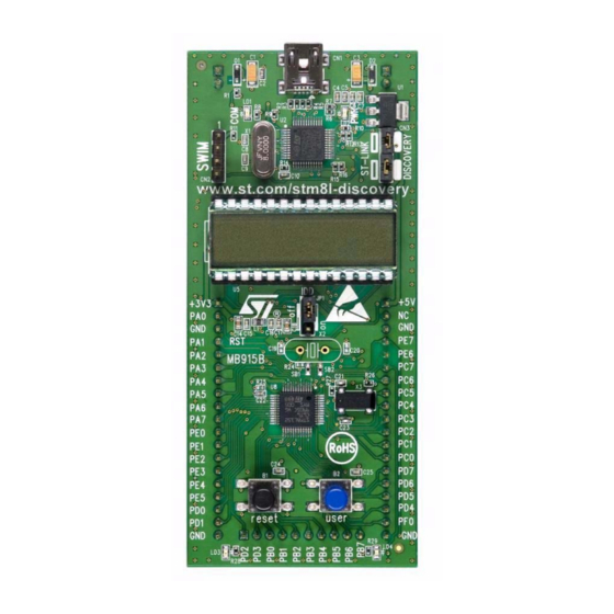
The STM8L-DISCOVERY helps you to discover the STM8L ultralow power features and to
develop and share your applications. It is based on an STM8L152C6T6 and includes an ST-
Link embedded debug tool interface, LCD (24 segments, 4 commons), LEDs and push
buttons.
Figure 1.
STM8L-DISCOVERY board
September 2010
Doc ID 17693 Rev 1
1/29
www.st.com
Downloaded from
Elcodis.com
electronic components distributor
Advertisement
Table of Contents

Related Manuals for ST STM8L-DISCOVERY


Summary of Contents for ST STM8L-DISCOVERY
- Page 1 The STM8L-DISCOVERY helps you to discover the STM8L ultralow power features and to develop and share your applications. It is based on an STM8L152C6T6 and includes an ST- Link embedded debug tool interface, LCD (24 segments, 4 commons), LEDs and push buttons.
-
Page 2: Table Of Contents
Embedded ST-Link ........ -
Page 3: Quick Start
Getting started Check jumper positions on the board, JP1 and CN3 ON (Discovery selected). Connect the STM8L-DISCOVERY board to a PC with a USB cable to power the board. Red LED LD2 (PWR) then lights up. Function 1 is executed and each click on user button B2 changes the executed function... -
Page 4: Development Toolchain
LCD the consumption of the MCU in run and low power modes. The latest versions of this demonstration source code and associated documentation can be downloaded from www.st.com/stm8l-discovery. Order code To order the STM8L ultralow power Discovery, use the order code STM8L-DISCOVERY. 4/29 Doc ID 17693 Rev 1 Downloaded from Elcodis.com... -
Page 5: Features
STM8L152C6T6 microcontroller, 32 KB Flash, 2 KB RAM, 1 KB EEPROM in 48-pin LQFP ● On-board ST-Link with selection mode switch to use the kit as a stand-alone ST-Link (with SWIM connector for programming and debugging) ● Two red LEDs; LD1 for USB communication, LD2 for 3.3 V power on ●... -
Page 6: Hardware And Layout
Hardware and layout UM0970 Hardware and layout The STM8L-DISCOVERY is designed around the STM8L152C6T6 microcontroller in a 48- pin LQFP package. Figure 2 illustrates the connections between the STM8L152C6T6 and its peripherals (ST- Link, push button, LED, LCD and connectors). - Page 7 UM0970 Hardware and layout Figure 3. Top layout D2 diode D1 diode power ST-Link SWIM connector ST-Link/Discovery selector IDD module LCD 24 segments measurement power supply input +3.3V power supply input SB1,2 X2 crystal STM8L152C6T6 Reset button User button LED blue...
- Page 8 Hardware and layout UM0970 Figure 4. Bottom layout SB3,5,7,9 PRG-32 (RESERVED) SB4,6,8,10 DEFAULT SB11,12,14 IDD_Measurement connector connector SB13,15 X3 crystal SB17 B2-USER SB16 B1-RESET connector 8/29 Doc ID 17693 Rev 1 Downloaded from Elcodis.com electronic components distributor...
-
Page 9: Stm8L152C6T6 Microcontroller
Analog functional down to 1.8 V, programming down to 1.65 V: Full functionality over the complete V range For more information see the STM8L152C6T6 datasheet (Doc ID 15962) on the ST website. Doc ID 17693 Rev 1 9/29 Downloaded from Elcodis.com... - Page 10 Hardware and layout UM0970 Figure 6. STM8L152C6T6 block diagram 10/29 Doc ID 17693 Rev 1 Downloaded from Elcodis.com electronic components distributor...
-
Page 11: Embedded St-Link
Hardware and layout Embedded ST-Link The ST-Link programming and debugging tool is integrated on the STM8L-DISCOVERY. The embedded ST-Link can be used in 2 different ways according to the jumper states (see Table ● to program/debug the MCU on board, ●... -
Page 12: Using The St-Link To Program/Debug The Stm8L On Board
Jumpers on CN3 3.2.2 Using the ST-Link to program/debug an external STM8L application It is very easy to use the ST-Link to program the STM8L on an external application. Simply remove the 2 jumpers from CN3 as shown in Figure... -
Page 13: Power Supply And Power Selection
USB connector is not connected to the PC. LEDs ● LD1 COM: Red LED indicates communication in progress between PC and ST-Link. ● LD2 PWR: Red LED indicates that the board is powered. -
Page 14: Built-In Idd Measurement Circuit
Hardware and layout UM0970 Built-in IDD measurement circuit The STM8L-DISCOVERY built-in I measurement circuit allows the consumption of the STM8L152C6T6 to be measured and displayed on the LCD Glass while the MCU is in Run or Low power saving modes. -
Page 15: Low Power Mode Idd Measurement Principle
After wakeup the MCU can measure the IDD current corresponding to the Low power mode stored in C11. Figure 11. STM8L-DISCOVERY I Low power mode measurement timing diagram The Low power mode measurement procedure can be used in Halt or Active halt mode if the... -
Page 16: Ibias Current Measurement Procedure
Hardware and layout UM0970 3.6.4 Ibias current measurement procedure In Low power mode the bias current of operational amplifier input (U4 pin 4) is not negligible compared to I current (typical Ibias is ~240 nA). To obtain a reliable STM8L152 I measurement it is mandatory to subtract the bias current from the I low power measurement since this current is not sinked by the MCU. -
Page 17: Lcd (24 Segments, 4 Commons)
UM0970 Hardware and layout LCD (24 segments, 4 commons) This LCD allows the STM8L152C6T6 to display any information on six 14-segment digits and 4 BARs, using all COMs. (See the LCD segment mapping in Figure 12 and pin connections in Table Note: This LCD also supports six 8-segment digits by only using COM0 and COM1. - Page 18 Hardware and layout UM0970 Table 5. LCD connections STM8L152C6T6 Pin name COM3 COM2 COM1 COM0 PA7_LCDSEG0 PE0_LCDSEG1 1COLON PE1_LCDSEG2 PE2_LCDSEG3 2COLON PE3_LCDSEG4 PE4_LCDSEG5 3COLON PE5_LCDSEG6 PD0_LCDSEG7 4COLON PD2_LCDSEG8 PD3_LCDSEG9 BAR2 BAR3 PB0_LCDSEG10 PB1_LCDSEG11 BAR0 BAR1 PD1_LCDCOM3 COM3 PA6_LCDCOM2 COM2 PA5_LCDCOM1 COM1 PA4_LCDCOM0 COM0...
-
Page 19: Extension Connection
UM0970 Extension connection Male headers P1, P2 and P3 can connect the STM8L-DISCOVERY to a standard prototyping/wrapping board. All GPI/Os of STM8L152C6T6 are available on it. P1, P2 and P3 can also be probed by an oscilloscope, logical analyzer or voltmeter. - Page 20 UM0970 Extension connection Table 6. P1 pinout (continued) Pin number Pin number Board pin Main Alternate function LCD (U5) (P1) (STM8L) name function PE5/LCD_SEG6(2)/ ADC1_IN23/ I/O Port E5 LCD_SEG6 COMP2_INP/ COMP1_INP PD0/TIM3_CH2/ [ADC1_TRIG](3)/ LCD_SEG7(2)/ I/O Port D0 LCD_SEG7 ADC1_IN2 2/ COMP2_INP/ COMP1_INP PD1/TIM3_TRIG/...
- Page 21 UM0970 Extension connection Table 7. P2 pinout (continued) Pin number Pin number Main Pin name Alternate function LCD (U5) (P2) (STM8L) function PC3/[USART1_TX](3)/ LCD_SEG23(2)/ I/O Port C3 ADC1_IN5/ LCD_SEG23 COMP1_INP/ COMP2_INM PC2/[USART1_RX](3)/ LCD_SEG22/ I/O Port C2 ADC1_IN6/ LCD_SEG22 COMP1_INP/ VREF_OUT I/O Port C1 PC1(4)/I2C1_SCL I/O Port C0...
- Page 22 Extension connection UM0970 Table 8. P3 pinout Pin number Pin number Main Pin name Alternate function LCD (U5) (P3) (STM8L) function PD2/TIM1_CH1 / LCD_SEG8(2)/ I/O Port D2 LCD_SEG8 ADC1_IN20/ COMP1_INP PD3/ TIM1_TRIG/ LCD_SEG9(2)/ I/O Port D3 LCD_SEG9 ADC1_IN1 9/ COMP1_INP PB0/TIM2_CH1/ LCD_SEG10(2)/ I/O Port B0...
-
Page 23: Electrical Schematics
Electrical schematics Figure 13. STM8L-DISCOVERY ST_LINK.SCHDOC IDD_measurement.SchDoc U_ST_LINK U_Power IDD_CNT_EN RESET# EXT_5V IDD_CNT_EN RESET# IDD_Measurement ST_LINK_SWIM IDD_Measurement ST_LINK_SWIM IDD_WAKEUP EXT_5V IDD_WAKEUP EXT_5V EXT_3V3 EXT_3V3 MCU.SchDoc GH08172_buttons.SchDoc U_MCU U_Power PC3_LCDSEG23 PC3_LCDSEG23 PA[0..7] PA[0..7] PC2_LCDSEG22 PC2_LCDSEG22 PB[0..7] PB[0..7] PD7_LCDSEG21 PD7_LCDSEG21 PC[0..7] PC[0..7]... - Page 24 PD6_LCDSEG20 PB3_LCDSEG13 PD7_LCDSEG21 PB2_LCDSEG12 PC2_LCDSEG22 PA4_LCDCOM0 PC3_LCDSEG23 PA5_LCDCOM1 GH08172T PA7_LCDSEG0 PA6_LCDCOM2 PE0_LCDSEG1 PD1_LCDCOM3 PE1_LCDSEG2 PB1_LCDSEG11 PE2_LCDSEG3 PB0_LCDSEG10 PE3_LCDSEG4 PD3_LCDSEG9 PE4_LCDSEG5 PD2_LCDSEG8 PE5_LCDSEG6 PD0_LCDSEG7 STMicroelectronics Title: STM8L-DISCOVERY LCD MB915 B.2(SCH.PCB) Date: 7/15/2010 Number: Rev: Sheet Downloaded from Elcodis.com electronic components distributor...
- Page 25 IDD_Measurement SB11 +3V3 +3V3 +3V3 74H1G66STR 2(1%) 2K(1%) +3V3 IDD_WAKEUP STT5PF20V +3V3 SB12 STT5PF20V +3V3 100nF 74LX1G04CTR IDD_CNT_EN SB14 M74HC4060TTR Oscillator frequency 30KHz STMicroelectronics Title: STM8L-DISCOVERY IDD_Measurement MB915 B.2(SCH.PCB) Date: 7/15/2010 Number: Rev: Sheet Downloaded from Elcodis.com electronic components distributor...
- Page 26 PD2_LCDSEG8 PB3_LCDSEG13 PD3_LCDSEG9 PB2_LCDSEG12 PB0_LCDSEG10 PB1_LCDSEG11 PA[0..7] STM8L152C6T6 PA[0..7] PB[0..7] PB[0..7] PC[0..7] PC[0..7] PD[0..7] PD[0..7] PE[0..7] PE[0..7] VDD_MCU VDDA BEAD 100nF 100nF 100nF STMicroelectronics Title: STM8L-DISCOVERY MCU MB915 B.2(PCB.SCH) Date: 7/15/2010 Number: Rev: Sheet Downloaded from Elcodis.com electronic components distributor...
- Page 27 Figure 17. ST-Link (SWIM only) ST_LINK_SWIM RESET# 100K +3V3 SWIM_IN SWIM +3V3 +3V3 STM_JTCK SWCLK STM32F103C8T6 SWIM_RST_IN SWIM_RST 20pF 20pF STM_JTMS SWDIO +3V3 +3V3 8MHz SB10 VBAT VDD_2 PC13 VSS_2 STM_JTMS PC14 JTMS USB_DP SWIM_PULLUP_CTL PC15 PA12 OSC_IN USB_DM OSC_IN...
-
Page 28: Revision History
Revision history UM0970 Revision history Table 9. Document revision history Date Revision Changes 24-Sep-2010 Initial release. 28/29 Doc ID 17693 Rev 1 Downloaded from Elcodis.com electronic components distributor... - Page 29 No license, express or implied, by estoppel or otherwise, to any intellectual property rights is granted under this document. If any part of this document refers to any third party products or services it shall not be deemed a license grant by ST for the use of such third party products or services, or any intellectual property contained therein or considered as a warranty covering the use in any manner whatsoever of such third party products or services or any intellectual property contained therein.
Need help?
Do you have a question about the STM8L-DISCOVERY and is the answer not in the manual?
Questions and answers