Advertisement
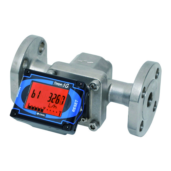
FLOWPET-5G
Electronic Register STARTUP GUIDE
Thank you for choosing the FLOWPET-5G.
・ This Startup Guide provides basic information that is
helpful for starting the use of the FLOWPET-5G electronic
register. For detailed explanation of the FLOWPET-5G's
functions and operation instructions, refer to the accompa-
nying instruction manual before use.
・ Please keep this Startup Guide handy for quick reference.
2. OPERATION BUTTONS
・The push buttons for operation (MODE and RESET) are located on the back of the display.
Left back: MODE button
Right back: RESET button
4. WIRING (for models with output capability)
①Pulse output type
②Analog output + Pulse output type
※1 : SIG.1 and SIG.2 can generate pulses by built-in battery power without external power source.(Battery life is 8 years approximately.)
For analog output only model, leave the ends of SIG.1 and SIG.2 cables open since they will not be used. Alarm output is optional.
8. DISPLAY MENU TREE
Under "Review Mode", setting changes to the items listed
below and using special functions such as "Simulated
Output" are available.
Item
Description
Pon
Factored pulse width [ms] setting
Pu
Factored pulse weight [L/P] setting
Analog output full scale [L/h] setting
AF
(Flow indicator display is linked to this setting.)
AdAn
Analog output damping [sec.] setting
LooPtESt Simulated output at arbitrary flow rate
⇒Refer to the corresponding sections in the instruction
manual for the procedures such as changing each
parameter and operating the simulated output function
[NOTE]
All parameters are set before shipment based on the
specifications at the time of order receipt, and generally
there is no need for the users to perform parameter
setting. Proper flow measurement may be unavailable if
parameter setting is performed inappropriately. Please
avoid performing unnecessary changes to the param-
eters. (Confirm the corresponding sections in the instruc-
tion manual thoroughly in case it is necessary to make
parameter changes.)
Please read before installation and use
OPERATING CONDITIONS
To maintain high accuracy and long life of this meter, it is necessary that the meter
be used within the specified conditions in flow rate, pressure, temperature and
viscosity. These operating conditions are stated on the nameplate of the register.
Confirm the contents of the nameplate thoroughly before installation and operation.
PRECAUTIONS ON INSTALLATION LOCATION
(1) In this register, a magnetic sensor is used to pick up magnetic fields of signaling
magnets embedded in the rotor. For this reason, the FLOWPET should be
installed sufficiently away from sources generating magnetic field. If a magnetic
valve of 10 watts or so is used, separate it at least 10 centimeters from the
flowmeter (varies with operating conditions).
(2) For applications in cold regions, install the meter indoors (boiler room, for
example) to prevent accidents caused by freezing.
①A vertical run is recommended for ease of pipeline drainage. Provide a drain
plug.
②When installing lagging, do not lag the electronic register, strainer cover, and
drain plug. Also, make sure of ready separation of the meter from the piping
assembly. NOTE: Refer to the corresponding sections in the instruction
manual for piping details.
(3) This register operates at the temperature range of -10 to +60゜ C. To ensure its
operation within the specified temperature range, protect the register with a
sunshade or heat shield if exposure to elevated temperatures by direct sunlight,
reflected heat, etc., is expected.
(4) This register is designed for indoor use: install the meter in a location free from
rainwater, oil, or sunlight. If exposure to such environment is unavoidable,
provide appropriate weather protection or sunshade.
All specifications in this startup guide are subject to change without
notice for improvement in performance and product quality.
OVAL Corporation
Phone. 81-3-3360-5121 Fax. 81-3-3365-8605
PUSH!
BRO SUP.: Power +
※1
GRY SIG.1: Factored pulse (or Alarm 1)
←max. 20mA
※1
WHI SIG.2: Unfactored pulse (or Alarm 2)
←max. 20mA max.
max. 30V
30V
GRN COM: 0V
NOTE: Leave the shielded wire open at its end (no contact). To extend the
cable, make sure to use shielded wire and extend the shield as well.
4 to 20mA Analog output
BRO SUP.: Power +
Load resistance: R
※1
GRY SIG.1: Factored pulse (or Alarm 1)
←max. 20mA
DC
※1
WHI SIG.2: Unfactored pulse (or Alarm 2)
←max. 20mA max.
max. 30V
30V
GRN COM: 0V
NOTE: Leave the shielded wire open at its end (no contact). To extend the
cable, make sure to use shielded wire and extend the shield as well.
.
※1
1. GENERAL SPECIFICATIONS
Item
Local display
function
Display accuracy
Display orientation
Flow detection
Cable
Transmission
distance
Power source
Ambient temperature
Material
Configuration
3. BASIC OPERATION PROCEDURE (MEASURE MODE)
Accumulated total
MODE
Instant flow rate: L/h
MODE
Instant flow rate: L/m
MODE
Resettable total
MODE
5. OUTPUT SPECIFICATIONS
Output type
・Open drain output (equivalent of open collector)
Factored pulse
・Allowable current: 20mA, Max. voltage applied: 30V
(Adjustable at [Pon] parameter within the range of 1 to 999ms in 1ms increments.)
・Open drain output (equivalent of open collector)
Unfactored pulse
DC
・Allowable current: 20mA, Max. voltage applied: 30V ・Pulse width: 2ms (fixed)
12 to 50V
Analog
・4 to 20mA output (using power wire) ・Acceptable load resistance: see figure below.
6. ACCEPTABLE LOAD RESISTANCE RANGE 7 . STANDARD PULSE UNIT
1900
L
600
12 to 50V
0
12
Power supply voltage (VDC)
※2: Unless otherwise specified, pulse unit is set according to factored pulse unit listed in the above table. For the official
specification at the time of shipment, please confirm the nameplate on the actual product.
※3: Full scale values of "Flow indicator display" and "Analog output" will be max. flow rate values in the table above.
(For oil-service models, the actual rated maximum flow rate varies by types of oil.)
Accumulated total
None
XXXXXXXX [□]
Instant flow rate (hourly)
NOTE: Goes back to the screen before
b1
b1±XXXXX [□/h]
switching to Review Mode
Instant flow rate (per-minute)
b2
b2±XXXXX [□/min]
Resettable total
C
CXXXXXXX [□]
:Transition made by pressing "MODE" switch
:Transition made by keeping "MODE" switch pressed for more than 5 seconds
:Transition made by pressing "RESET" switch
Total flow related data
Instant flow related data
totAL
rAtE
F
Meter factor
AF
Full scale flow rate
Conversion factor
Damping
H
Ad A
n
Pu
Pulse weight
bP
Instant flow decimal point
At
Sampling time
Po n
Pulse width
Indicated unit
Sampling cycle number
Un
A
SP
Total flow decimal point
d. o1
Digital output 1 assign.
d.o2
Digital output 2 assign.
NOTE: Not displayed on standard
specification. (Displayed only on
d.o3
Digital output 3 assign.
※3
alarm option specified models)
Specification
Display mode
Display mode symbol
①Accumulated total (8-digit)
None
②Instantaneous flow rate, L/h (5-digit)
b 1
③Instantaneous flow rate, L/m (5-digit)
b2
④Resettable total (7-digit)
C
Within ±1 count
Total flow
Instantaneous flow rate
Within ±1% of full scale
Display angle adjustable in 15° steps
(Adjust the angle up or down by hand to find
easy-to-view position)
Magnetic sensor detects alternating magnetic fields. (200Hz max.)
1m of vinyl-sheathed, 4-conductor shielded cable (individual elements AWG24)
furnished as standard (Not furnished with models without pulse generator)
Either Pulse or Analog
Max. 1km
output used
(CVVS: 1.25 to 2.0mm
Max. 100m
Pulse + Analog output
(CVVS: 1.25 to 2.0mm
both used
3.6VDC dedicated battery built-in, Battery life: 8 years (varies with operating conditions)
Storage life: 10 years
Lithium
・Battery icon blinks as the battery starts to run out.
・If equipped with pulse output capability, pulse generation can be done just with built- in
battery
battery without an external power source. (If supplied with external power source, lithium
battery will not be consumed.)
12 to 50VDC±10% (consumption current: Max. 30mA)
External
power source
(For analog output, refer to "6. Acceptable load resistance range")
-10 to +60℃ (no condensing)
Polycarbonate (black)
IP65 (Install indoors or under the eaves. Avoid exposure to direct sunlight.)
Each time the MODE button is pressed, the screen scrolls through
flow displays; select the desired flow display.
(Accumulated total → Instantaneous flow: L/h → Instantaneous flow:
L/m → Resettable total)
The flow indicator at the bottom of the display indicates % of actual flow
(instantaneous flow rate) to the full scale flow rate.
NOTE: Full scale flow rate (flow rate which represents 100%) is determined in
the parameter: AF. (AF value is also applied to the analog output full scale value
of analog output specification)
※1:About the display during MODE button operation
①Normal operation
When the MODE button is
pressed:
On the resettable total display,
⇒8 bars appear.
zero-reset will be performed on
total flow by pressing the RESET
button.
⇒Immediately turning OFF
(letting go of the button)
scrolls the display to the
RESET
next one.
Specification
Nom.
Model
size
mm
LS5277
20
LS5377
25
LS5577
40
Operating
LS5677
50
range
LS4976
20
LS5076
20
LS5276
25
LS5376
40
24
50
LS5576
40
LS5676
50
:Holding the MODE switch pressed for more than 2 seconds at this
display changes the Review Mode to the Write Mode. The following
operations are enabled in the Write Mode:
①Pressing the MODE switch moves the digit one place to the left.
②Pressing the RESET switch increases the figure by one.
③Holding the MODE switch pressed for more than 2 seconds again
changes the mode back to the Review Mode.
: Title
(Titles describe the attributes of each parameter stored under each
title: They are not settable parameters.)
:Switching to Write Mode from these displays will allow operators to
use special functions such as analog trims and simulated output.
Analog trim
AL
Alarm data
A
nA
.tri.
Alarm 1 setting
A04
A1
d
4mA trim
Alarm 1 hysteresis
A20
A1
H
20mA trim
A1
S
Alarm 1 status
Alarm 2 setting
A2
d
NOTE: Displayed only on analog
output equipped models.
Alarm 2 hysteresis
A2
H
A2
S
Alarm 2 status
※1: During Review Mode, the information icon is
displayed on the upper right corner of the screen.
※2: Parameter symbols are displayed at flow rate unit display
area.
※3: This product does not use d.o3 mode setting.
Ins. No. S -179-SU-1-E
Selectable with MODE button
Zero resettable with RESET button
2
)
2
)
②Long-press operation
When the MODE button is
kept pressed down:
⇒Bars begin to disappear
one by one from the left
⇒Holding the MODE button down
until the last bar disappears
executes long-press process
(Switching between Normal
mode and Review mode, or
finalizing the parameter setting,
etc.). If turned OFF (releasing
the MODE button) before the
last bar disappears, the same
operation as ①Normal operation
will take place.
※2
Unfactored
Factored
pulse
pulse
Max.
flow rate
Pulse
Output
Nominal
Output
unit
freq.
meter
freq.
※3
factor
L/P
Hz
mL/P
Hz
L/h
1
0.33
9.918
33.6
1200
1
1.00
17.955
55.7
3600
10 0.20
35.496
56.3
7200
10 0.33
76.455
43.6
12000
1
0.22
5.928
37.5
800
1
0.56
9.912
56.0
2000
1
1.05
9.639
109.5
3800
1
1.77
17.47
101.8
6400
10 0.38
34.526 112.6 14000
10 0.66
74.483
89.5
24000
Simulated output
Service mode
LooP
tESt
88888888
Simulated instant flow value
Input frequency display
S.b
I.F r
S.c
Simulated total flow value
Operating time
O.t
Flow operating time
StArt
Simulated output
F.t
No. of MODE switch press
SWM
※2
SWR
No. of RESET switch press
※2
Energy Savemode setting
ES. bt.
FC.r
Factory reset
SoFt.
Software revision
Advertisement
Table of Contents


Need help?
Do you have a question about the Flowpet-5G and is the answer not in the manual?
Questions and answers